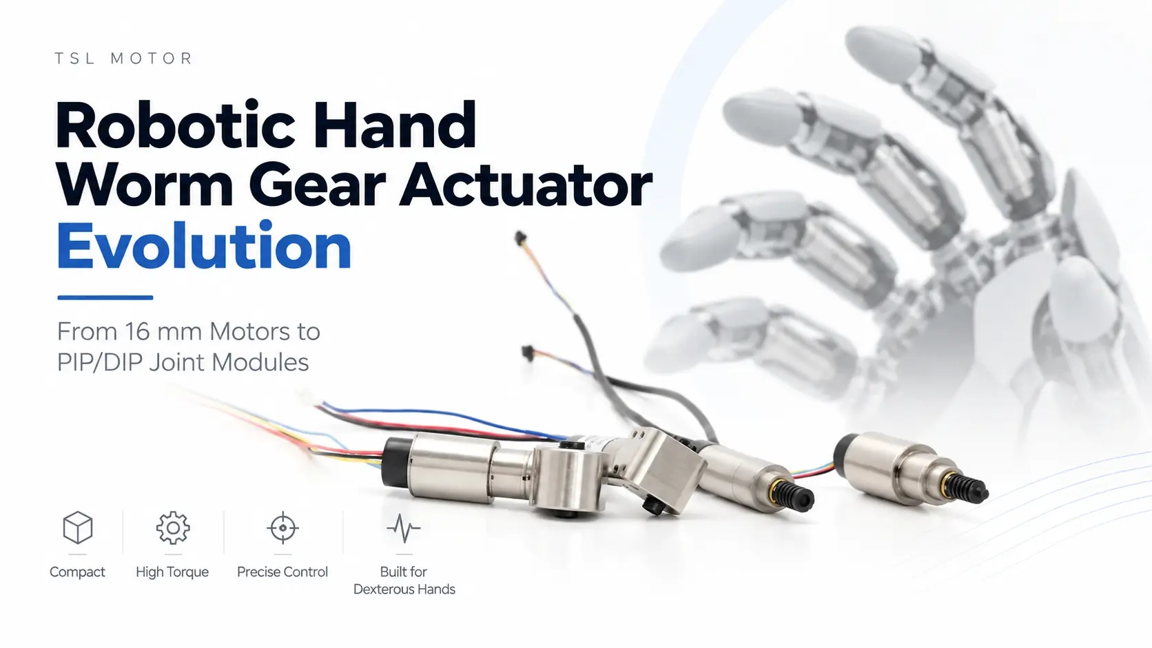

A robotic hand worm gear actuator may look like a relatively simple combination of a motor, planetary gearbox, and worm drive. In practice, developing one for a compact dexterous hand requires much more than reducing motor diameter.
Motor size, available torque, gearbox ratio, backlash, encoder configuration, wiring, installation tolerance, thermal behavior, and production consistency all affect whether an actuator can actually move from prototype testing into stable production.
TSL MOTOR has been developing worm-drive actuator platforms for robotic hands for several years. During that period, the architecture has changed repeatedly—from relatively large 16 mm brushed systems to compact 10 mm and 13 mm brushless actuator modules with integrated sensing and motor control.
The ten stages below represent the major design changes. Numerous smaller revisions occurred between them and are not listed individually.
At a Glance
The development path can be summarized as:
16 mm brushed motor + worm drive
→ 8 mm coreless motor
→ brushless motor + encoder
→ integrated planetary carrier and worm shaft
→ integrated worm-drive actuator
→ 10 mm actuator platform
→ housing integration
→ 13 mm thumb platform
→ integrated driver and four-wire control
→ shorter PIP/DIP production modules
The result is no longer simply a geared motor. It is becoming a complete joint actuation platform.
First Generation: 16 mm Brushed Planetary Gear motor + Worm Drive
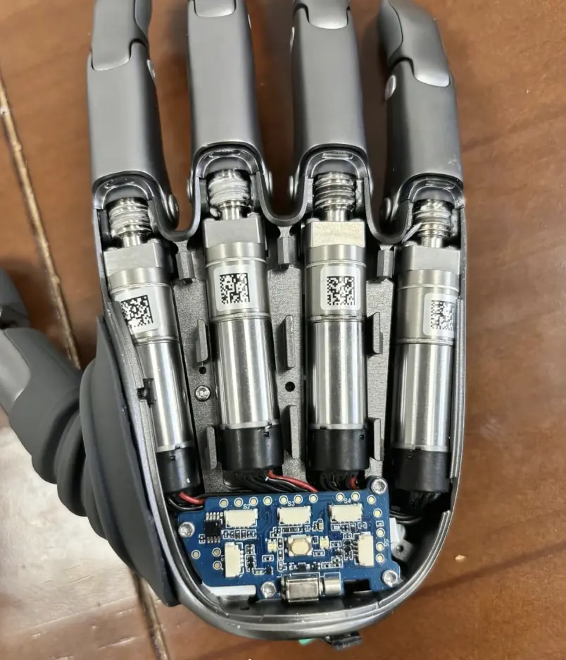
Our earliest robotic-hand architecture used a 16 mm brushed motor, planetary gearbox, and external worm transmission.
This first generation proved that a miniature motor combined with a high reduction ratio could generate sufficient torque for finger-joint actuation.
However, its limitations were also obvious.
Both the motor section and the worm head were relatively large. As more actuators had to be packaged inside the same robotic hand, the available internal volume quickly became the dominant constraint.
The next development objective therefore became clear:
reduce the actuator envelope without losing useful joint output.
Second Generation: Moving to an 8 mm Brushed Coreless Motor
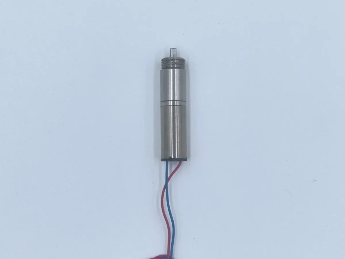
The second generation reduced the motor diameter from 16 mm to 8 mm.
A brushed coreless motor was paired with a miniature planetary gearbox, significantly reducing the size of the drive unit.
At this stage, however, the worm and worm wheel remained separate components purchased and installed by the customer.
TSL MOTOR supplied the motor and planetary reduction section, while the customer completed the final worm-drive assembly.
This architecture worked well for early prototypes, but it also revealed an important problem:
the smaller the mechanism became, the more sensitive it was to customer-side assembly accuracy.
Third Generation: Brushless Motor and Encoder Feedback
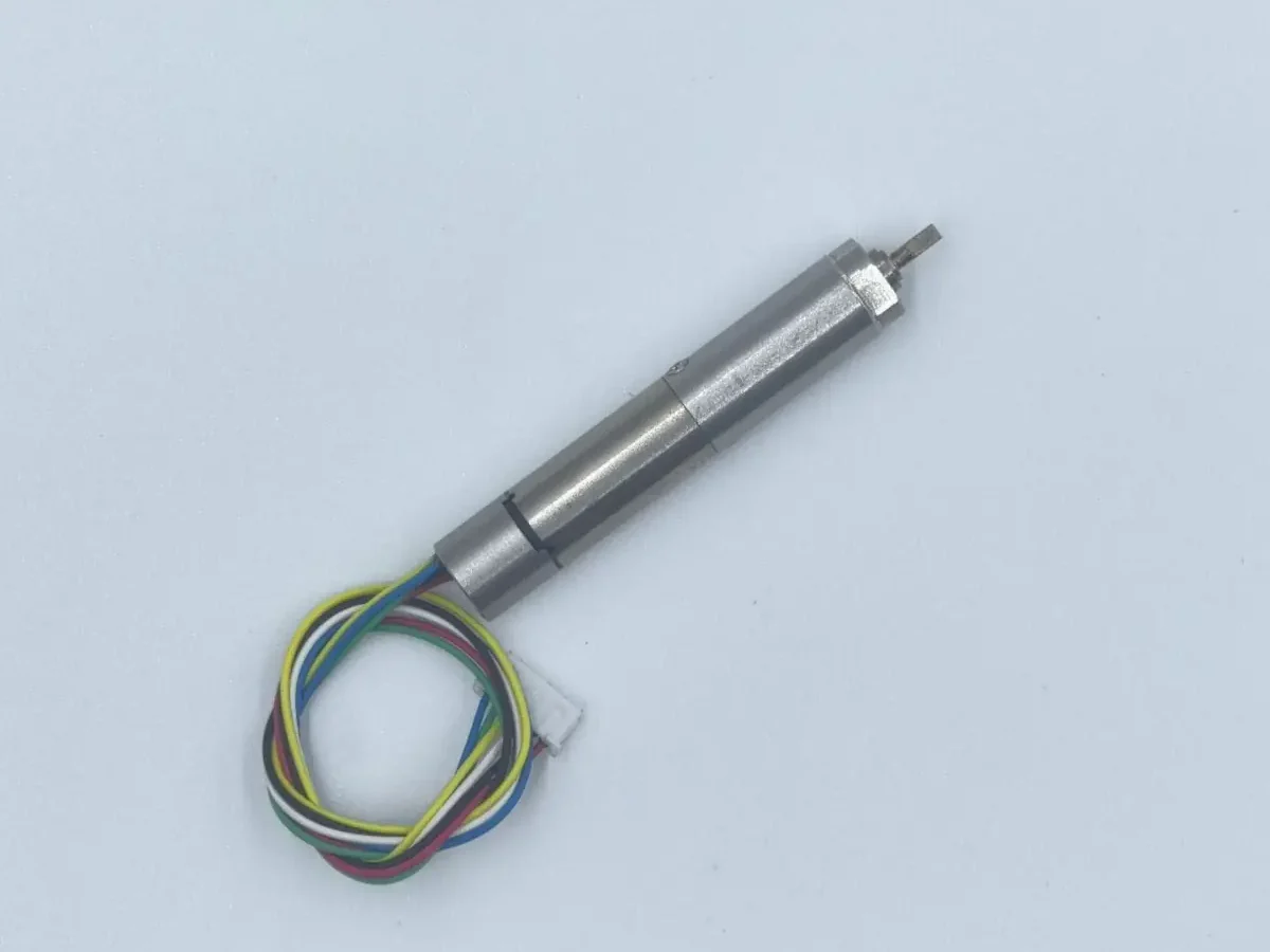
The third generation introduced a brushless coreless motor together with encoder feedback.
This allowed the actuator to move from basic open-loop power transmission toward more controlled motion.
As dexterous hands became more complex, repeatable joint positioning became increasingly important, and encoder feedback gradually became a standard requirement in many projects.
At this stage, the worm transmission was still installed separately by the customer.
The design problem was beginning to change from:
How much torque can the motor generate?
to:
How can motor output, mechanical transmission, and position feedback work together in a limited space?
Fourth Generation: Integrating the Planet Carrier and Worm Shaft
The fourth generation introduced an important mechanical change.
Instead of connecting a conventional planetary gearbox to a separate worm shaft, TSL MOTOR developed a structure in which the planet carrier and worm shaft were integrated into one component.
The system still used an 8 mm brushed coreless motor, while the worm wheel used a copper-alloy construction.
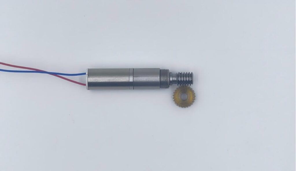
This reduced the number of mechanical interfaces and shortened the transmission chain.
More importantly, it marked the transition from supplying a geared motor toward developing the complete actuator transmission as one system.
Fifth Generation: Brushless Motor, Encoder and Reinforced FPC
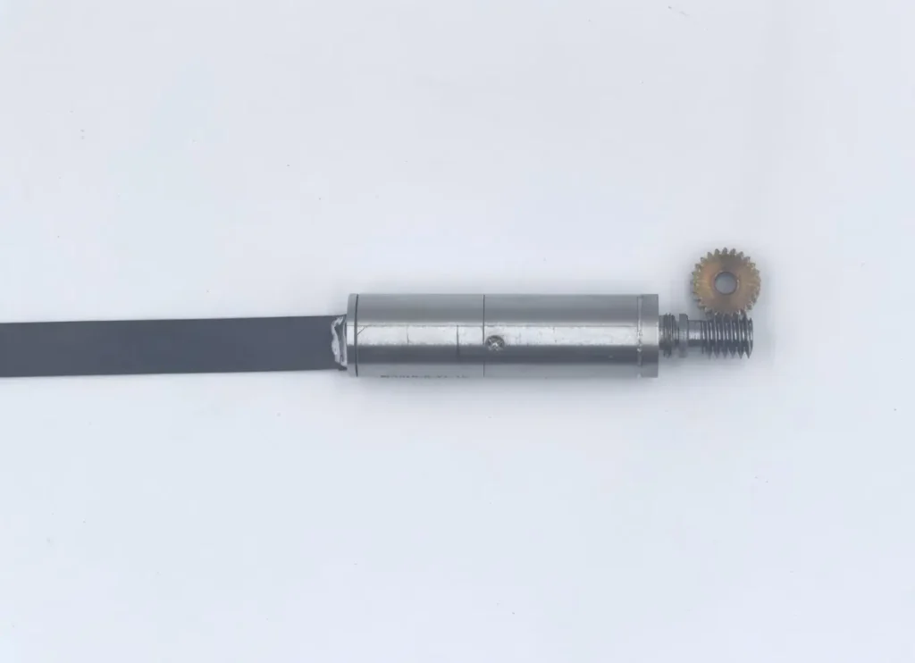
The fifth generation upgraded the platform again with a brushless motor, encoder feedback, and FPC wiring.
As the actuator became smaller, conventional wires occupied a relatively large amount of internal space. FPC therefore offered an attractive way to simplify internal routing.
TSL MOTOR later introduced reinforced FPC solutions designed to improve resistance to pulling and repeated movement.
This stage made one thing increasingly clear:
wiring is not a secondary issue in a dexterous hand.
Electrical connections are repeatedly bent, pulled, and routed through moving structures, making cable reliability part of the actuator design itself.
Sixth Generation: From 8 mm to the First 10 mm Actuator Module
Further customer testing showed that smaller was not always better.
For some joints, the 8 mm motor platform did not provide enough torque margin.
At the same time, when customers assembled the worm and worm wheel themselves, small installation errors could result in excessive backlash.
These issues led TSL MOTOR to develop the first major 10 mm integrated robotic hand worm gear actuator platform.
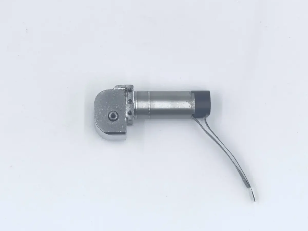
The design objective changed from minimizing diameter at all costs to balancing:
size, torque, backlash, durability, and assembly consistency.
For a production robotic hand, the smallest actuator is not necessarily the best actuator.
Seventh Generation: Improving the Worm Drive and Housing
The seventh generation further improved both the worm transmission and external housing.
One of the main objectives was to reduce the amount of precision assembly required by the customer.
Earlier architectures required customers to control the relative position of several transmission components during installation. Small deviations could affect backlash, operating smoothness, and consistency between joints.
By integrating more of these mechanical relationships into the actuator itself, TSL MOTOR made installation easier and more repeatable.
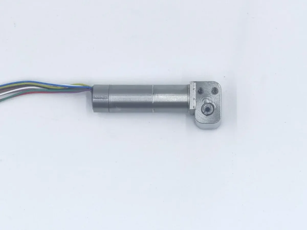
At this stage, the product was increasingly becoming a joint actuator module, rather than simply a motor combined with a gearbox.
Eighth Generation: 13 mm Platform for Thumb Joints
As more projects entered practical development, it became clear that a 10 mm actuator could not efficiently cover every robotic-hand joint.
The thumb is a typical example.
Some thumb applications required greater torque and more mechanical margin. At the same time, certain customers did not require a high-resolution encoder. Hall sensing already provided sufficient positioning accuracy for their application.
TSL MOTOR therefore developed a 13 mm actuator platform, including Hall feedback and an additional temperature-sensing line.
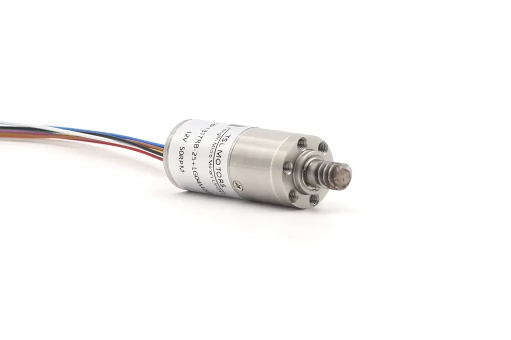
The platform subsequently entered stable volume production.
This led to an important engineering conclusion:
A robotic hand does not need to use the same actuator in every joint.
Thumb joints, MCP joints, PIP joints, and DIP joints may require different torque, packaging, feedback, and mechanical structures.
Ninth Generation: Two Product Families and Integrated Motor Control
Several smaller revisions occurred between the eighth and ninth major generations.
During this period, encoder configurations gradually stabilized around two main options:
- 1024 PPR incremental encoder
- 16-bit absolute encoder
The mechanical architecture also developed into two major product families:
worm-drive actuators without a complete housing, andfully housed worm-drive actuator modules.
Both 10 mm and 13 mm platforms entered volume production, while some 16 mm encoder-equipped products continue to be supplied for applications where additional space is available.
The largest ninth-generation change, however, was electronic integration.
TSL MOTOR developed a compact driver that can be mounted directly at the rear of the motor.
Together with our host-control software, the actuator can be operated through only four external wires.
This greatly reduces wiring complexity inside a multi-joint robotic hand.
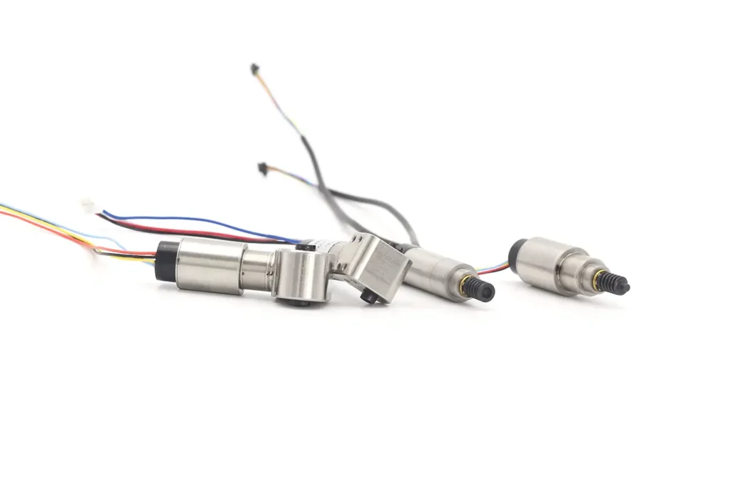
Instead of separately integrating the motor, encoder, driver, planetary gearbox, worm transmission, and communication wiring, customers can increasingly treat the complete system as one actuator module.
One current 13 mm production platform with integrated driver and encoder is also available through the online store for developers and research teams that want to evaluate a production-oriented actuator directly.
Tenth Generation: Shorter Platforms for PIP and DIP Joints
As more active joints move from the palm into the finger itself, actuator packaging becomes even more demanding.
PIP and DIP joints provide significantly less axial installation space than palm-mounted drive systems.
To address this requirement, TSL MOTOR developed new compact actuator platforms in which the motor body length has been reduced to approximately 10 mm, excluding the reduction mechanism.
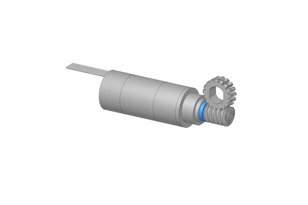
These compact platforms are not only laboratory prototypes. The corresponding actuator modules have already entered production.
The development question has therefore changed from:
Can the actuator fit inside the robotic hand?
Why TSL MOTOR Moved from FPC Back to PTFE Wires
One of the latest updates may appear to be a step backward.
Earlier generations moved from conventional wiring to FPC, and later to reinforced pull-resistant FPC.
The objective was straightforward: reduce wiring volume.
However, repeated motion in real dexterous hands showed that even reinforced FPC was not ideal in applications where the cable continuously experienced pulling or mechanical tension.
For the latest production platforms, TSL MOTOR therefore changed back to flexible, pull-resistant PTFE-insulated wires for these operating conditions.
From a packaging perspective, FPC may appear more advanced.
From a reliability perspective, however, PTFE wiring proved more suitable for certain dynamic applications.
This illustrates an important principle of actuator engineering:
A production improvement does not always mean using a more complex technology. Sometimes the better solution is simply the one that survives longer.
Why Customers Rarely Ask TSL MOTOR to Change the Output Speed
Another interesting pattern has emerged from our robotic-hand customization projects.
Customers frequently request changes to:
- torque;
- actuator diameter;
- mechanical interfaces;
- encoder configuration;
- wiring;
- voltage;
- communication;
- installation structure.
Output speed, however, is one of the parameters that customers ask us to change least frequently.
This does not mean that one universal speed is suitable for every robotic hand.
Instead, it suggests that the operating-speed range developed through several generations of TSL MOTOR worm-drive actuators already matches many practical finger-joint applications reasonably well.
As a result, recent development has focused increasingly on:
torque density, integration, reliability, backlash, sensing, wiring, installation, and control, rather than simply increasing speed.
Two Robotic Hand Worm Gear Actuator Families
The current TSL MOTOR robotic hand worm gear actuator platform has gradually stabilized into two main mechanical families.
Worm Drive Without Full Housing
This configuration gives customers more freedom to integrate the actuator into their own robotic-hand structure.
It is particularly suitable when the customer already has a mature mechanical housing and wants greater flexibility over the final joint design.
Fully Housed Worm-Drive Module
The fully housed version integrates more of the worm-wheel positioning and mechanical relationship directly into the supplied actuator.
This reduces customer-side precision assembly requirements and improves installation consistency between different joints.
Neither structure completely replaces the other.
They are intended for different robotic-hand architectures and customer integration strategies.
From a Micro Gearmotor to a Robotic-Hand Joint Platform
Looking back at these ten major generations, the development direction becomes clear.
The earliest question was:
Can a miniature motor generate enough joint torque?
Then it became:
How can the motor, planetary gearbox, and worm drive fit into a smaller space?
After that:
How can customer-side assembly backlash be reduced?
The next questions involved:
encoders, wiring, thermal sensing, mechanical housings, and installation consistency.
Today, the challenge has evolved again:
How can the motor, transmission, feedback system, driver, communication interface, and wiring operate as one production-ready joint module?
This is why TSL MOTOR increasingly describes these products as robotic-hand actuator modules, rather than simply miniature gearmotors.
Worm Drive Is Only One Development Path
This article focuses specifically on the robotic hand worm gear actuator platform.
It does not represent every robotic-hand transmission architecture currently being developed by TSL MOTOR.
Linkage-driven actuator systems follow a different mechanical design path and will be discussed separately in a future article.
TSL MOTOR is also developing other precision actuation technologies for applications outside compact robotic fingers.
For example, our planetary roller screw linear actuator platform is currently positioned primarily for medical applications. Its mechanical envelope is larger than the worm-drive modules discussed here, but the platform can achieve repeatability of approximately ±3 μm.
Its current application focus is medical equipment rather than dexterous hands, although similar high-precision linear-actuation principles may also have potential in future robotic systems.
The key point is simple:
there is no single actuator architecture suitable for every robotic joint.
Transmission technology should follow the application.
From Prototype to Volume Production
Many actuator concepts can work in a laboratory prototype.
The more difficult question is whether the same architecture remains practical after hundreds or thousands of units are assembled.
Volume production introduces additional requirements:
- consistent speed;
- consistent torque;
- repeatable backlash;
- stable encoder installation;
- wiring reliability;
- assembly tolerance;
- thermal behavior;
- customer-side installation repeatability.
This is why many major updates to TSL MOTOR actuators did not originate from theoretical performance improvements.
They came from real customer integration, repeated testing, and production feedback.
The transition from 16 mm to 8 mm, the move back to 10 mm, the development of 13 mm thumb platforms, integrated housings, encoder standardization, integrated drivers, four-wire control, and the recent change from FPC back to PTFE wires all followed the same objective:
make the actuator easier to integrate and more reliable in real robotic hands.
Conclusion
The development of a compact robotic hand worm gear actuator is not simply a process of making the motor smaller.
Across multiple generations, TSL MOTOR has gradually shifted from basic torque generation toward complete joint-level integration.
The current 10 mm and 13 mm platforms combine experience in:
coreless motor design,
planetary reduction,
worm transmission,
encoder feedback,
wiring,
motor control,
and production assembly.
PIP and DIP applications are pushing this development even further, requiring shorter motors and more compact joint-level integration.
At the same time, TSL MOTOR continues to develop linkage-driven architectures and other precision actuator technologies for different robotic applications.
There is no final generation.
As robotic hands continue to evolve, the actuators inside them must evolve as well.
FAQ
Q1. How does TSL MOTOR control temperature rise in its robotic hand actuators?
Under validated continuous operating conditions, TSL MOTOR robotic hand actuators can operate continuously for at least 2 hours without triggering thermal protection.
The actuator includes temperature monitoring, and the protection threshold is set at 90°C. If the monitored temperature reaches this limit, the drive automatically cuts power to protect the motor and actuator system.
Actual temperature rise depends on factors such as load torque, duty cycle, ambient temperature, installation conditions, and joint motion profile.
Q2. What encoder options are available for TSL MOTOR robotic hand worm gear actuators?
TSL MOTOR currently offers two main encoder configurations for its robotic hand actuator platforms:
- 1024 PPR incremental encoder
- 16-bit absolute encoder
The appropriate option depends on the joint control architecture, required position resolution, homing strategy, and communication system.
For some applications, such as certain thumb joints, a Hall-based position sensing solution may also provide sufficient accuracy while reducing system complexity.
Q3. Can the TSL MOTOR actuator be supplied with an integrated driver?
Yes.
TSL MOTOR has developed compact integrated drivers that can be mounted directly at the rear of the motor. With the integrated driver and TSL MOTOR host-control software, the actuator can be operated using only four external wires for power and communication.
This reduces wiring complexity inside multi-joint dexterous hands and simplifies system integration.
Driver, encoder, communication protocol, and mechanical configuration can be selected according to the project requirements.
Q4. Why does TSL MOTOR offer both housed and non-housed worm-drive actuator versions?
The two architectures are designed for different integration strategies.
The non-housed worm-drive version gives customers greater flexibility to integrate the motor and transmission into their own robotic-hand structure.
The fully housed actuator module integrates more of the worm-wheel positioning and mechanical relationships inside the actuator itself, reducing customer-side precision assembly and helping improve backlash and installation consistency.
Neither configuration is universally better. The appropriate choice depends on the customer’s mechanical architecture and manufacturing strategy.