
Sizing a planetary gear motor often starts with a formula that seems completely logical:
Output Torque = Motor Torque × Gear Ratio × Gearbox Efficiency
Suppose a motor produces 8 mN·m of torque at its target operating point, connected to a 64:1 planetary gearbox with an estimated efficiency of 75%.
Then: Calculated Output Torque = 0.008 N·m × 64 × 0.75 = 0.384 N·m
However, if the gearbox datasheet specifies a rated continuous torque of only 0.25 N·m, which value should engineers actually use? The 0.384 N·m figure is the transmittable output torque calculated from the motor’s operating point, gear ratio, and assumed efficiency.
The 0.25 N·m figure, on the other hand, is the maximum mechanical rated torque the gearbox is allowed to sustain continuously under specified lifetime, temperature rise, and operating conditions.
Therefore, torque available for continuous operation cannot be determined by formula calculations alone; it is strictly limited by the gearbox’s mechanical strength, bearing life, thermal capacity, and application duty cycle.
Key Takeaways
- Gear ratios increase output torque, but they do not increase mechanical power.
- Efficiency describes power transmission loss, not mechanical load capacity.
- Multiple planet gears operate as parallel load paths; their individual meshing efficiencies cannot simply be multiplied together.
- Multi-stage reduction functions as a series transmission, where efficiencies of each stage must be multiplied.
- The maximum efficiency listed in datasheets usually applies only to specific operating points.
- When calculated output torque exceeds the gearbox’s rated torque, the rated torque must serve as the upper limit for continuous operation.
- Continuous usable torque must be verified through temperature rise, bearing load, and lifespan testing.
What Does Planetary Gearbox Efficiency Actually Mean?
For the standalone gearbox:
Gearbox Efficiency (ηgb) = Output Mechanical Power (Pout) / Input Mechanical Power (Pin)
Rotational mechanical power is defined as:
P = T × ω
Where: P is mechanical power; T is torque; ω is angular velocity; ηgb is gearbox mechanical efficiency.
If the reduction ratio is defined as:
Gear Ratio (i) = Input Speed (ωin) / Output Speed (ωout)
Then output torque can be estimated as:
Tout = Tin × i × ηgb
This formula originates from conservation of power. A gearbox trades speed for torque, but it cannot create mechanical power. It is important to note that this formula only estimates the torque that could be transmitted to the output end at a given operating point—it does not prove that the gearbox can sustain this torque long-term.
Gear Ratio Increases Torque, Not Power
Suppose a motor outputs 0.01 N·m of torque at 6000 rpm. Its mechanical power input into the gearbox is approximately:
Pin = 0.01 × 2π × (6000/60) ≈ 6.28 W
After connecting a 20:1 gearbox, the ideal output speed is:
6000 / 20 = 300 rpm
Assuming zero losses, the ideal output torque would be:
0.01 × 20 = 0.20 N·m
The output power remains approximately 6.28 W. If the gearbox efficiency at this operating point is 85%, the actual estimated output is:
Output Power = 6.28 × 0.85 ≈ 5.34 W Output Torque = 0.01 × 20 × 0.85 = 0.17 N·m
Roughly 0.94 W of mechanical power is lost to gear meshing, bearings, and lubrication, primarily converting into heat. Thus, the gearbox accomplishes a conversion of:
High Speed, Low Torque ⟶ Low Speed, High Torque
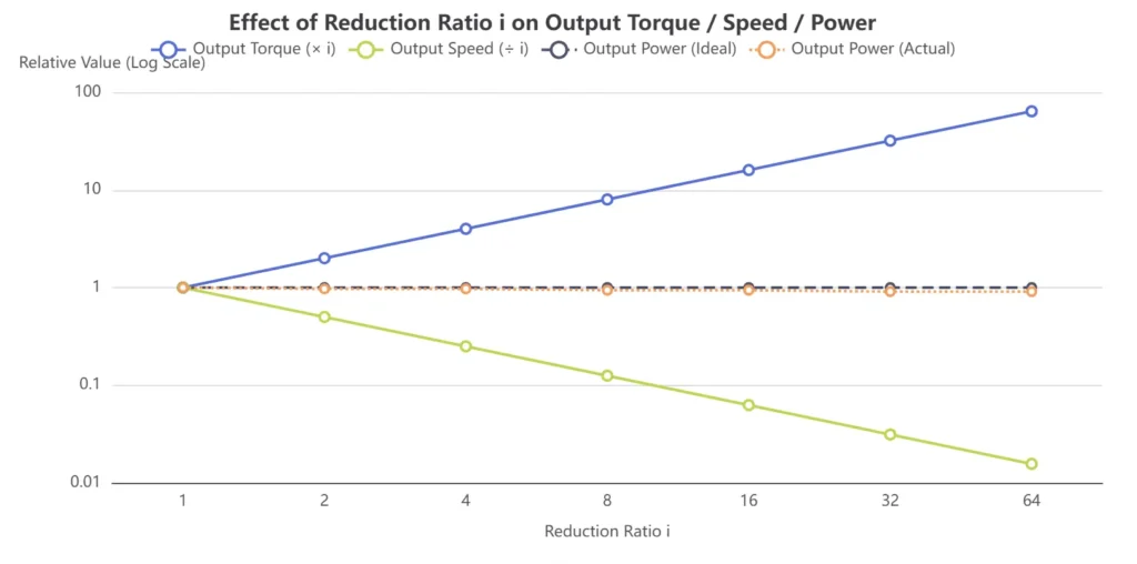
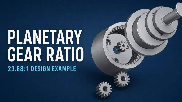
It does not increase total power. To further understand the speed ratio relationships between the sun gear, ring gear, and planet carrier, refer to Planetary Gear Ratio Calculation: 23.68:1 Two-Stage Design Example.
Where Do Power Losses in Planetary Gearboxes Come From?
Losses in planetary gearboxes do not stem from a single point; they arise from multiple concurrent mechanical processes.
Load-Dependent Losses
As transmitted torque increases, the following losses typically rise:
- Meshing friction between the sun gear and planet gears;
- Meshing friction between planet gears and the internal ring gear;
- Deformation of gear teeth under load;
- Friction at planet pins and planet gear bearings;
- Uneven tooth contact and misalignment under load;
- Deformation of the planet carrier under load.
Speed-Dependent No-Load Losses
Even under minimal output load, the gearbox still experiences:
- Bearing viscous resistance;
- Grease shearing losses;
- Rotational drag of the planet carrier;
- Drag caused by gears churning through lubricant;
- Losses from lubricant squeezing and displacement between teeth;
- Seal friction.
Consequently, a “light load” does not imply an efficiency close to 100%.
In miniature planetary gearboxes, fixed losses from grease and bearings can account for a substantial percentage of total power. Stating “gearbox efficiency is 95%” without specifying load, speed, and temperature offers very limited engineering value.
Three Planet Gears Do Not Mean Multiplying Efficiency Six Times
A typical single-stage structure with three planet gears contains three sun-to-planet meshing pairs and three planet-to-ring meshing pairs.
However, these planet gears represent parallel power paths rather than six gear pairs connected in series. Therefore, you cannot simply raise a single-mesh efficiency to the 6th power.
The number of planet gears primarily affects:
- Load distribution;
- Load borne by individual gear teeth;
- Planet carrier stiffness;
- Theoretical load-carrying capacity;
- Smoothness of operation;
- Sensitivity to manufacturing and assembly errors.
Furthermore, having three planet gears does not guarantee perfectly equal load sharing. Gear accuracy, planet pin location errors, carrier deflection, and assembly concentricity all influence actual load distribution.
Multi-Stage Reductions Require Compounding Efficiency
While multiple planet gears operate in parallel within one stage, multiple reduction stages function in series.
Therefore: Total Efficiency = Stage 1 Efficiency × Stage 2 Efficiency × … × Stage n Efficiency
Assuming a per-stage efficiency of 90% for illustrative purposes:
| Reduction Stages | Estimated Total Efficiency |
|---|---|
| Single-Stage (1-Stage) | 90% |
| Two-Stage (2-Stage) | 81% |
| Three-Stage (3-Stage) | 72.9% |
| Four-Stage (4-Stage) | 65.6% |
These figures are not universal for all planetary gearboxes. Real-world efficiency depends on gear ratio, module, gear precision, materials, bearings, lubricants, temperature, and input speed.
Why Is Efficiency Not a Fixed Value?
The “maximum efficiency” listed in datasheets is measured under specific load, speed, lubrication, and temperature conditions. It does not mean the gearbox operates at this efficiency across all operating points.
Influence of Load
Under light loads, output power drops while bearing friction and lubrication drag do not decrease proportionally. As a result, fixed losses take up a larger percentage, yielding lower net efficiency. As load increases, the relative proportion of fixed losses decreases and efficiency rises. However, as load increases further, gear tooth friction, bearing loads, and structural deflections escalate, preventing efficiency from increasing indefinitely.
Influence of Speed
At low speeds, fixed friction losses may dominate; at high speeds, bearing viscous losses, grease shearing, and churning drag increase. Thus, identical gear ratios and output torques may yield different efficiencies at varying input speeds.
Influence of Temperature
Low temperatures increase grease viscosity, raising startup torque and no-load losses. As temperature rises, viscous resistance decreases; however, excessive temperatures degrade grease, bearings, and non-metallic materials, shortening operational lifespan.
Influence of Lubrication
Insufficient lubrication accelerates wear, whereas excessive grease increases churning resistance. Miniature planetary gearboxes are exceptionally sensitive to grease type, fill quantity, and distribution.
Therefore, datasheet maximum efficiency cannot be blindly applied to startup, light-load, low-temperature, or continuous full-load operating conditions.
Why Can Calculated Output Torque Be Higher Than Rated Torque?
These two parameters answer fundamentally different questions.
Transmittable Output Torque
Tavailable = Tmotor × i × ηgb
Question answered: Based on current motor operating conditions, gear ratio, and transmission efficiency, how much torque can theoretically reach the output shaft?
Gearbox Rated Torque
Continuous Usable Torque ≤ min(Ttransmittable, Tgearbox_rated, Tmotor_thermal_rated, Shaft/Bearing Limit, Temp/Life Limit)
Question answered: Under specified duty cycles, temperatures, and lifetime requirements, how much output torque is the gearbox mechanically permitted to sustain continuously?
Gearbox rated torque may be constrained by:
- Sun gear and planet gear root bending strength;
- Tooth surface contact fatigue and pitting;
- Planet pin bending and contact stress;
- Planet carrier rigidity and fatigue life;
- Planet gear bearing lifespan;
- Output shaft and output bearing limits;
- Internal ring gear and housing support limits;
- Lubrication state;
- Target operating lifespan.
Therefore, practical continuous output evaluation requires that:
- Torque transmittable by the motor after efficiency correction;
- Rated continuous torque of the gearbox;
- Thermal continuous torque of the motor;
- Permissible load of output shaft and bearings;
- Allowable temperature rise and service‑life limits for the application.
Siemens servo planetary gear motor technical documentation, for instance, separately lists motor thermal continuous torque, gearbox rated torque, gearbox acceleration/maximum torque, and integrated gear motor rated torque. This distinction highlights that just because a motor can generate a certain torque does not mean the gearbox can transmit it continuously.
Efficiency, Mechanical Strength, and Lifespan Must Be Evaluated Separately
- Efficiency answers: What percentage of input mechanical power successfully reaches the output end?
- Rated Torque answers: What mechanical load can the gearbox safely sustain long-term under defined conditions?
A gearbox can be highly efficient yet possess a low rated torque due to small sun gears, slender planet pins, or limited bearing capacity. Conversely, a rugged gearbox designed for heavy loads might exhibit lower efficiency due to multi-stage arrangements, seals, or heavy lubrication drag.
ISO 6336-1:2019 provides a calculation framework for the load capacity of spur and helical gears, covering failure modes like pitting and tooth breakage. However, the standard explicitly notes that gear calculations alone do not guarantee complete transmission system performance. Even if gear tooth strength meets specifications, the entire gearbox may still be limited by planet pins, carriers, bearings, output shafts, housings, or lubricant life.
Do Not Confuse Continuous, Periodic, Peak, and Emergency Stop Torques
Professional gearbox datasheets explicitly differentiate:
- Continuous torque (Nominal torque);
- Periodic/intermittent torque;
- Maximum / acceleration torque;
- Emergency stop torque;
- Permissible radial and axial loads.
Peak torque exceeding continuous torque is not a data contradiction—it reflects differing durations and fatigue limits.
Thermal Limits May Become the Real Continuous Output Boundary
Power lost in the gearbox is primarily converted into heat:
Ploss = Pin − Pout = Pin × (1 − η)
Suppose a gearbox outputs 10W of mechanical power at $80\%$ efficiency:
Pin = 10 / 0.80 = 12.5 W
Ploss = 12.5 − 10 = 2.5 W
While 2.5W of heat dissipation might be negligible for large industrial gearboxes, it is substantial for a micro planetary gearbox with a diameter of just $12\text{ mm}$.
Temperature rise can further impair:
- Grease viscosity and operating life;
- Motor winding temperature;
- Bearing operating state;
- Permanent magnet properties;
- Dimensions and strength of plastic components;
- Fit tolerances between housing and bearings;
- Overall gear motor lifespan.
ISO/TR 14179-1 utilizes thermal equilibrium models to analyze gearbox thermal capacity. This demonstrates that meeting mechanical strength requirements does not guarantee a gearbox can operate continuously without thermal overload.
A prototype operating at 0.30 N·m for 10 seconds merely proves it survived that 10-second burst—it does not prove 0.30 N·m is a viable continuous rating.
How Should 0.384 N·m and 0.25 N·m Be Used?
Revisiting the initial scenario:
- Motor operating point torque: 8 mN·m
- Gear ratio: 64:1
- Estimated efficiency: 75%
- Calculated transmittable torque: 0.384 N·m
- Gearbox rated continuous torque: 0.25 N·m
If the load requires 0.20 N·m continuous torque: 0.20 N·m < 0.25 N·m < 0.384 N·m
The motor side possesses sufficient theoretical drive capacity. The gearbox rated continuous torque exceeds the load requirement. Preliminary mechanical sizing passes. Next step: Verify temperature rise, bearing loads, and target lifespan.
If the load requires 0.30 N·m continuous torque: The motor can theoretically deliver 0.30 N·m through the gearbox.
However, 0.30 N·m exceeds the gearbox’s 0.25 N·m continuous rating. Therefore, 0.30 N·m cannot be approved as a continuous operating point.
The calculated 0.384 N·m figure retains value because it indicates torque margin on the motor side. However, motor torque margin does not automatically increase the mechanical load rating of the gearbox.
What Do Actual Product Data from TSL MOTOR Show?
TSL-PG12-KS1215: System Efficiency Across Gear Ratios
The TSL-PG12-KS1215 micro planetary gear motor offers reduction ratios of 5:1, 25:1, 125:1, and 625:1.
Using the rated voltage, current at peak efficiency point, and output power published on the product page, we can calculate overall gear motor system efficiency:
System Efficiency (ηsystem) = Output Mechanical Power / Electrical Input Power
| Gear Ratio | Current at Max Efficiency | Electrical Input Power | Output Power | Estimated System Efficiency |
|---|---|---|---|---|
| 5:1 | 46.3 mA | 0.556 W | 0.29 W | ~52.2% |
| 25:1 | 56.5 mA | 0.678 W | 0.27 W | ~39.8% |
| 125:1 | 52.0 mA | 0.624 W | 0.25 W | ~40.1% |
| 625:1 | 47.8 mA | 0.574 W | 0.22 W | ~38.4% |
This calculation represents the total system efficiency from electrical input to gearbox output shaft—not standalone gearbox efficiency. It accounts for:
- Motor copper loss;
- Brush and commutator electrical losses;
- Motor iron losses;
- Motor bearing friction;
- Planetary gear meshing losses;
- Gearbox bearing and lubrication losses.
Therefore, it is incorrect to state that “the efficiency of a 625:1 gearbox is 38.4%.”
A precise description is: At the published maximum efficiency operating point, the entire 12V gear motor with a 625:1 ratio has an electrical-to-mechanical system efficiency of approximately 38.4%.
TSL-PG16-KW1636: Higher Gear Ratios Do Not Yield Proportionally Higher Output Power
The TSL-PG16-KW1636 gear motor offers ratios of 30:1, 157:1, 850:1, and 4592:1. At each version’s peak efficiency point, output power decreases from approximately 1.65W to 0.65W.
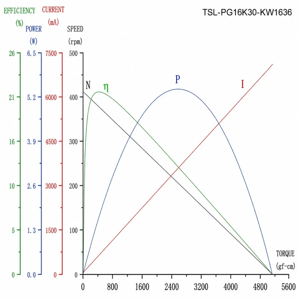
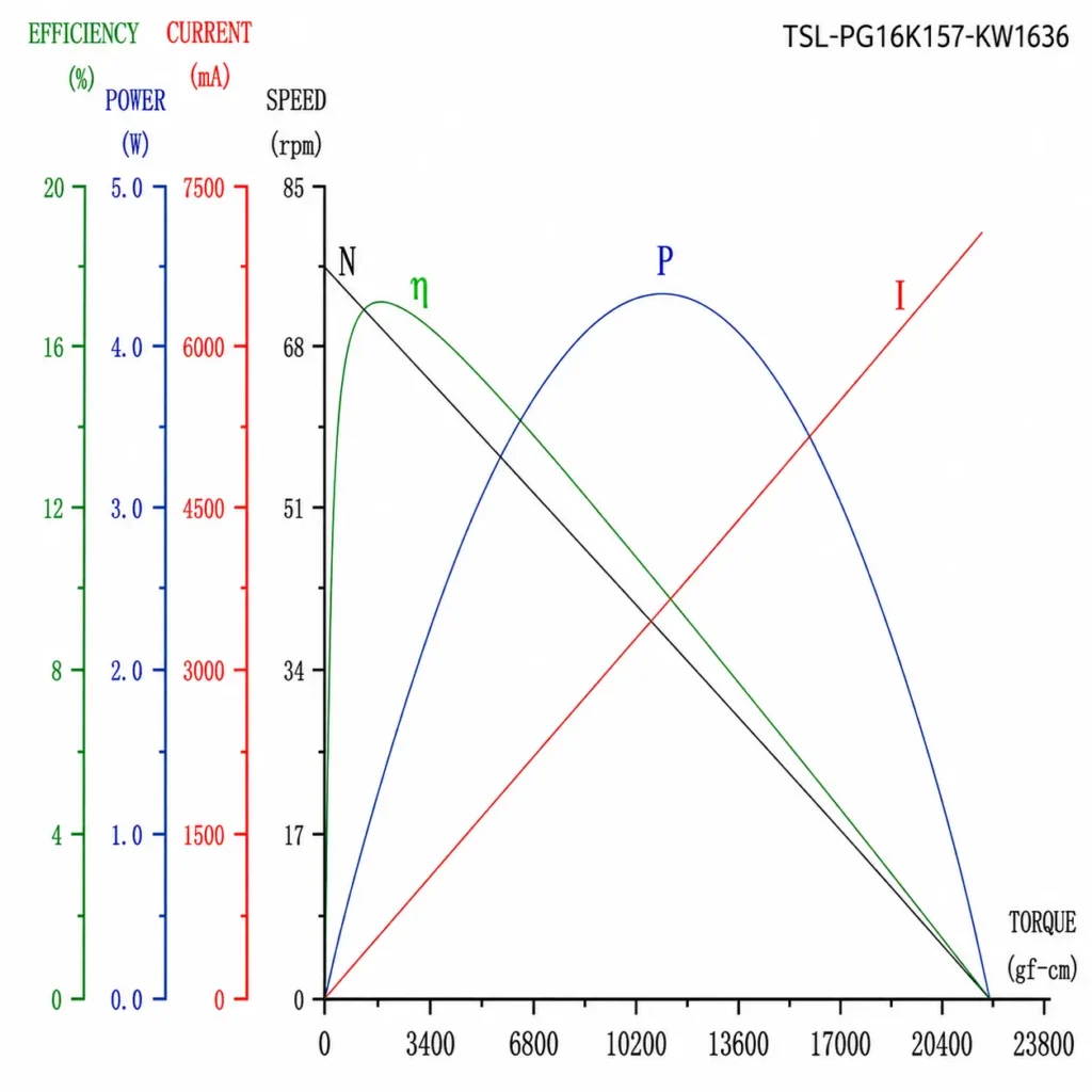
While these data points do not isolate motor losses from gearbox losses, they clearly demonstrate that as reduction ratio and stage count increase, output power drops and torque does not scale endlessly with nominal gear ratio. Multi-stage meshing losses, motor operating points, low-speed friction, and mechanical gear limits all constrain the final output.
What Is the Difference Between Gearbox Efficiency and Gear Motor System Efficiency?
Gearbox Mechanical Efficiency:
ηgb = Gearbox Output Mechanical Power / Gearbox Input Mechanical Power Measures mechanical reduction losses exclusively
Gear Motor System Efficiency:
ηsystem = Output Shaft Mechanical Power / Electrical Input Power Combines motor and gearbox losses
Under simplified conditions:
ηsystem ≈ ηmotor × ηgb
For example, if motor efficiency is 70% and gearbox efficiency is 80%: ηsystem ≈ 70% × 80% = 56%
Even if a planetary gearbox achieves 95% mechanical efficiency, the integrated gear motor system efficiency will be significantly lower.
Gear materials, manufacturing precision, and lubrication methods also affect friction, temperature rise, noise, and allowable load. For further differences, please refer to our comparison of micro planetary gear materials: Steel, Powder Metallurgy, and POM. We won’t repeat the material selection discussion here.
How to Correctly Read Planetary Gearbox Datasheets?
Before applying formulas, determine the measurement boundary for each parameter:
| Data Type | Common Parameters | Measured Location |
|---|---|---|
| Motor Data | Motor torque, speed, current | Motor shaft / Gearbox input |
| Gearbox Data | Gear ratio, mechanical efficiency | Gearbox body |
| Output Data | Output speed, output torque | Gearbox output shaft |
| Mechanical Limits | Continuous, periodic, peak torque | Gearbox output shaft |
| Electrical Data | Voltage, current, input power | Electrical input terminals |
Additionally, verify parameter classifications:
- Measured test points vs. typical values;
- Nominal / rated values vs. maximum/peak limits;
- Upper or lower bounds.
If a datasheet lists “Rated Output Torque,” do not multiply this value by the gear ratio again—the reduction ratio has already been factored into output-side specifications.
Perform Quick Power Balance Checks
Suppose a calculation claims an output torque of 0.30 N·m at 100 rpm: Output Power = 0.30 × 2π × (100/60) ≈ 3.14 W
If the same dataset claims mechanical input power to the gearbox is only 2 W, the numbers are physically impossible. Passive gearboxes cannot generate power.
Power balance sanity checks quickly expose:
- Unit conversion errors;
- Inverted gear ratio calculations;
- Confusion between motor-side and output-side parameters;
- Double-counting reduction ratios;
- Unrealistic efficiency assumptions.
Correct Gear Motor Sizing Workflow
- Determine required load continuous torque, peak torque, and output speed.
- Calculate required load mechanical power.
- Select candidate gear ratios based on motor operating speed.
- Verify actual motor output torque at the target speed.
- Estimate gearbox efficiency based on target load, speed, and temperature.
- Calculate transmittable output torque.
- Compare calculated output torque with gearbox rated continuous torque.
- Check peak torque duration and duty cycle limits.
- Verify output shaft radial, axial, and tilting moment capacity.
- Validate continuous operating temperature rise.
- Evaluate gear, bearing, and lubrication lifespan against target operating hours.
- Perform actual prototype load and durability testing.
Once the basic diameter, reduction ratio, output speed, and rated torque are determined, you can compare existing standard models within the TSL MOTOR planetary geared motor product line. The rated output torque listed on the product pages can be used directly for initial continuous load screening.
Common Calculation Errors
| Common Error | Why It Is Incorrect |
|---|---|
| Multiplying motor torque by gear ratio without efficiency | Ignores power transmission losses. |
| Applying a single fixed efficiency across all operating points | Efficiency fluctuates with load, speed, and temperature. |
| Multiplying efficiency by the number of planet gears | Planet gears form parallel load paths, not series stages. |
| Treating calculated output torque as rated torque | Mechanical limitations of the gearbox have not been checked. |
| Assuming higher gear ratios always yield proportionally higher usable torque | High ratios require more stages, increasing friction and mechanical constraints. |
| Sizing continuous operation based on peak torque | Peak torque is only permissible for short intermittent bursts. |
| Equating system efficiency with gearbox efficiency | System efficiency includes motor electrical/mechanical losses. |
| Multiplying rated output torque by gear ratio | Double-counts the gear ratio effect. |
| Sizing continuous operation using stall torque | Stall torque occurs at zero speed and is not a continuous operating point. |
| Relying on a few seconds of testing to validate continuous rating | Short tests fail to expose thermal equilibrium and long-term fatigue life. |
Conclusion
The efficiency of a planetary gearbox is a power transmission parameter, not a mechanical torque rating.
The following formula can be used to estimate the theoretical output torque a motor can provide after passing through a gearbox:
Transmissible Output Torque = Motor Operating Point Torque × Gear Ratio × Actual Efficiency
However, for Micronix standard gearmotors, customers do not need to separately look up the continuous allowable torque of the gearbox. The product pages directly provide the rated output torque of the complete gearmotor assembly, which serves as the primary basis for conventional continuous load selection.
For example, if a theoretical calculation yields 0.384 N·m, but the rated output torque listed on the Micronix product page is 0.25 N·m, the 0.25 N·m value must be used for continuous applications. Theoretical calculations are useful for verifying the motor-side capability, but they cannot override the manufacturer’s published ratings.
For projects involving non-standard gear ratios, frequent start-stop cycles, extreme temperatures, special life requirements, or shock loads, Micronix can also provide or calculate the individual continuous allowable torque, peak torque, output shaft loads, and thermal limits of the gearbox.
When submitting a project inquiry, please provide the output speed, continuous torque, peak or starting torque, operating voltage, duty cycle, ambient temperature, installation space, axial and radial loads, and target lifespan. Based on this information, TSL MOTOR can evaluate and propose customized motor and planetary gear transmission solutions.
FAQ
Q1:How high is planetary gearbox efficiency typically?
There is no single fixed efficiency for all planetary gearboxes. Efficiency depends on structure, stage count, gear ratio, input speed, load, lubrication, and temperature. Maximum values in datasheets represent specific test conditions.
Q2:Why does calculated output torque exceed rated torque?
Calculated torque indicates what the motor could theoretically transmit through the gearbox, whereas rated torque is the mechanical limit the gearbox can safely sustain continuously. Tooth fatigue, planet pins, bearings, shaft strength, temperature rise, and target lifetime often cap rated torque below calculated values.
Q3:Must efficiency be multiplied for each stage of a planetary gearbox?
Yes. For multi-stage gearboxes connected in series, total efficiency is estimated by multiplying the efficiency of each stage. However, planet gears within the same stage operate in parallel and should not be multiplied by planet count.
Q4:Can maximum efficiency be used to calculate startup torque?
Generally no. At startup, speed, lubrication state, and motor current differ significantly from the peak efficiency point. Cold starts also increase grease viscosity and mechanical drag.
Q5:Is it safe if calculated output torque is lower than rated torque?
Not necessarily. Motor temperature rise, gearbox thermal capacity, peak loads, radial/axial shaft forces, duty cycles, and target lifetime must still be verified.