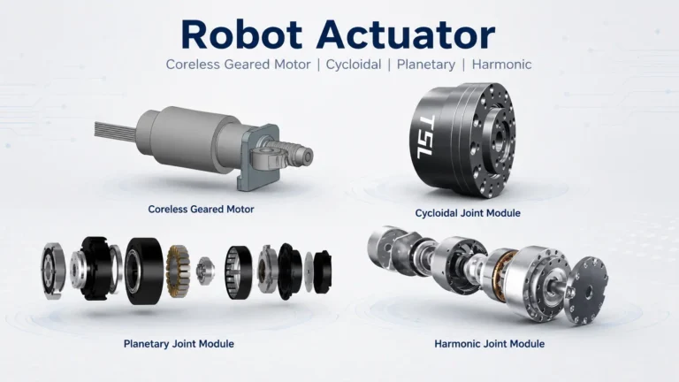
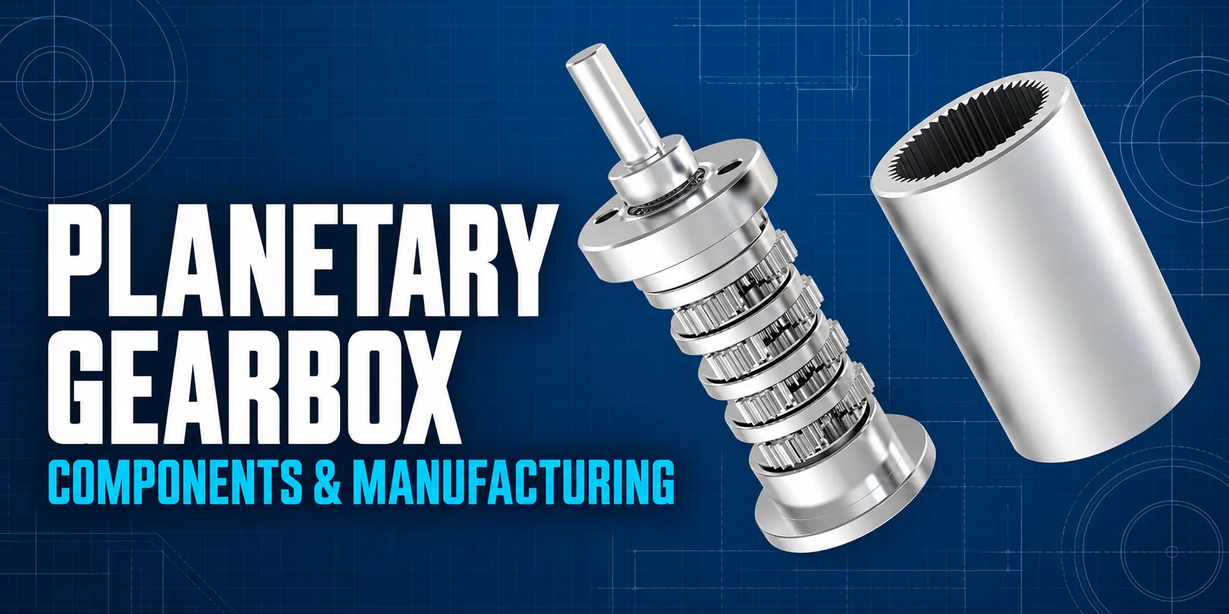

In robotic finger drives, compact medical mechanisms and precision instruments, planetary gearboxes convert a motor’s high-speed rotation into the lower speed and higher torque required by the mechanism.
However, two gearboxes with the same diameter and reduction ratio may still perform very differently. Gear geometry, planet-pin-hole position, carrier rigidity, and the locating references between the flanges and housing all affect whether the gears mesh evenly and smoothly.
Understanding how a planetary gearbox is manufactured requires examining component function and machining method as part of the same tolerance chain.
This article focuses on TSL Motor steel-geared planetary gearboxes. It explains the functions and manufacturing methods of the ring gear, sun gear, planet gears, carrier, planet pins, end flanges, output shaft and bearings, before comparing steel machining with plastic injection molding and powder metallurgy. Available configurations can be found in the TSL Motor planetary gear motor range.
Key Takeaways
- Dimensional inspection and assembled-gearbox testing determine the final manufacturing quality..
- The common planetary arrangement uses a fixed ring gear, an input sun gear and an output carrier.
- The planet gears rotate around their own axes while orbiting the sun gear.
- The planet pins transfer the gear load to the carrier.
- TSL Motor hobs the steel sun and planet gears and CNC-machines the carrier and planet pins.
- Selected ring gears may require precision wire EDM for tighter profile accuracy.
- Manufacturers injection-mold plastic gears and compact and sinter powder-metallurgy gears.
Separate Transmission Components from Support Components
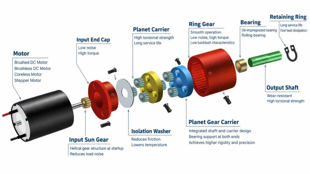
A planetary gearbox is not simply a group of gears installed inside a cylindrical housing. The sun gear, planet gears and ring gear form the meshing system. The carrier and planet pins control the positions of the planet gears, while the housing, flanges, bearings and bushings provide support and location.
In a multistage gearbox, the carrier of one stage commonly drives the sun gear of the next stage. However, the actual connection method and component count must always be confirmed from the assembly drawing.
| Component | Structural Function | Manufacturing and Inspection Focus |
|---|---|---|
| Sun Gear | Central input gear in a common planetary arrangement | Tooth profile, pitch, and the position of the mounting bore or shaft journal relative to the teeth |
| Planet Gear | Meshes with both the sun gear and ring gear while rotating around a planet pin | Tooth accuracy, bore size, and the relationship between the end face and bore axis |
| Internal Ring Gear | Provides the internal meshing surface and carries reaction torque when fixed | Internal tooth profile, pitch, roundness, and tooth position relative to the mounting reference |
| Planet Carrier | Locates the planet pins and combines the loads transmitted by the planet gears | True position of the pin holes, bore size, parallelism and structural rigidity |
| Planet Pin | Supports planet-gear rotation and transfers load to the carrier | Outside diameter, cylindricity, surface finish, fit and retention method |
| End Flange or End Plate | Provides mounting, location, bearing support or axial retention, depending on the design | Locating pilot, bearing bore, face runout, mounting holes and axial dimensions |
| Output Shaft or Lead Screw | Transfers output torque or converts rotary motion into linear motion when used with a guided nut | Journal fit and runout; lead-screw pitch, connection method and load path |
| Bearing | Supports rotating components and carries radial or axial loads according to bearing type | Load capacity, mounting direction, fit, clearance or preload, and lubrication |
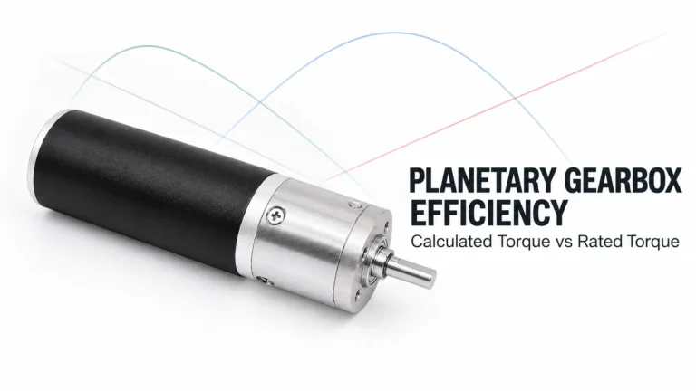
For a system-level explanation of how reduction ratio, output torque and gearbox losses interact, see Planetary Gearbox Efficiency: Why Does Calculated Output Torque Not Equal Rated Torque?.
Hobbing the Sun Gear and Planet Gears
In the TSL Motor steel-geared design discussed in this article, the external teeth of the sun and planet gears are produced by hobbing. Hobbing is a generating process in which the hob and gear blank rotate in a controlled relationship while continuous cutting forms the tooth profile.
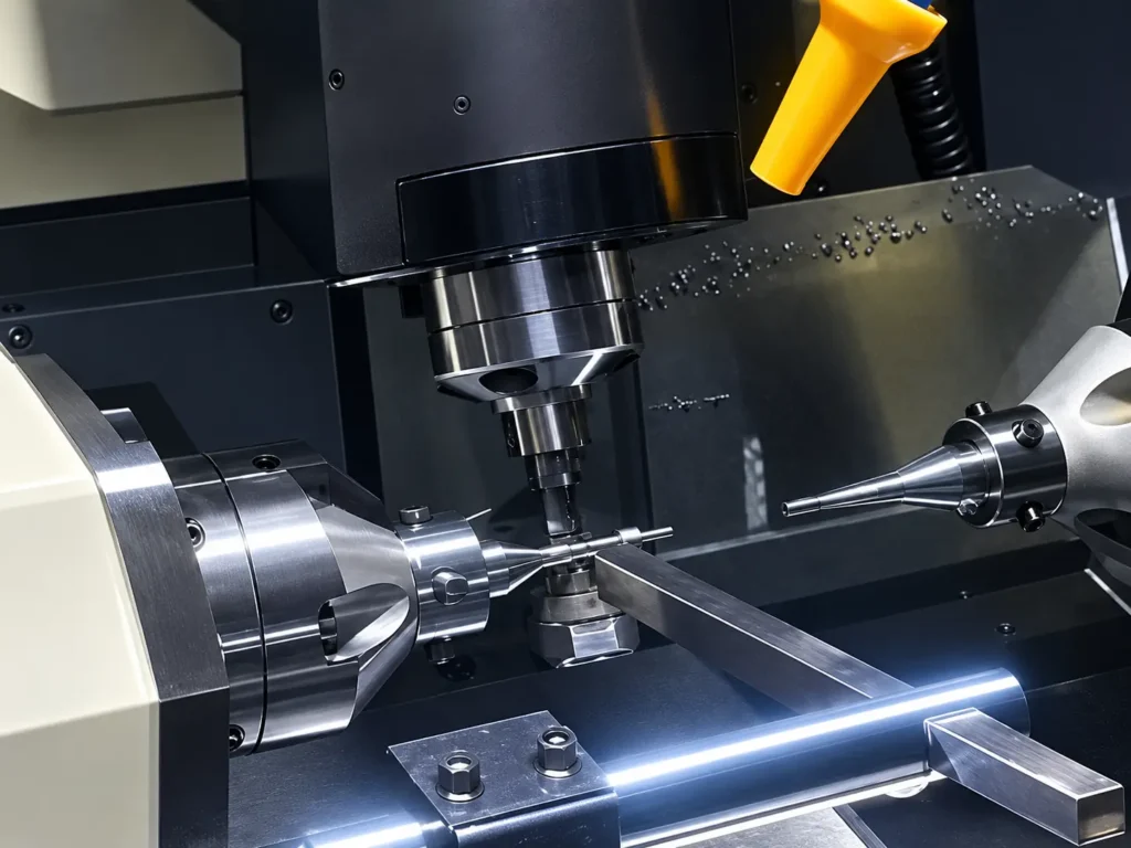
The term “steel gear” here refers to a manufacturing route in which the teeth are cut from a steel blank. It does not mean that every steel gear must be manufactured by hobbing.
Before hobbing, reliable machining references must be established. These may include the centre bore, shaft journal and end face of the blank. For a planet gear with a central bore, the position of the bore relative to the gear teeth affects meshing after assembly. For a sun gear manufactured integrally with its shaft, the concentricity between the support journals and the gear teeth becomes particularly important.
After hobbing, burrs around the tooth roots, end faces and bore edges must be removed carefully. Burrs or loose chips left inside a miniature gearbox can increase drag, damage tooth surfaces or interfere with lubrication.
Heat treatment and its preceding and subsequent operations must be arranged according to the selected steel, load and drawing requirements. A hobbed gear is not automatically a finished gear. If heat treatment causes distortion, the tooth profile, dimensions and runout must be rechecked. Grinding or another finishing process may be required when the specified accuracy or surface condition cannot be achieved directly after heat treatment.
CNC describes how a machine is controlled, while hobbing, turning and milling describe specific machining processes. These terms are not mutually exclusive.
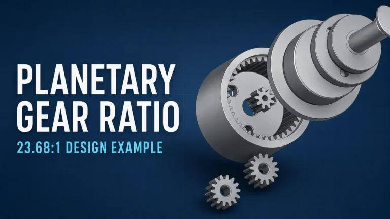
For non-standard tooth counts or reduction ratios, a drawable gear set is not necessarily ready for production. Tool compatibility, root interference, machining access and stage layout must be checked together, as explained in How to Calculate a Planetary Gear Ratio from Gear Tooth Counts.
Why Internal Ring Gears Require Different Manufacturing Routes
Why Conventional External Hobbing Cannot Be Applied Directly
The teeth of an internal ring gear are located on the inside of an annular component. Tool entry, cutting clearance and tool exit are therefore different from those of an external gear. Conventional external-gear hobbing usually cannot be applied directly to this structure.
Gear shaping, power skiving and, under suitable conditions, broaching are possible manufacturing routes that must be evaluated against the actual geometry. For example, Helios Gear Products identifies gear shaping as a suitable process for many internal gears and structures where hob clearance is restricted.
The manufacturing route should therefore not be simplified to “wire EDM for high accuracy and hobbing for low accuracy.” Gear shaping and power skiving can also produce accurate internal gears. The appropriate process depends on module, face width, material condition, tool interference, production volume and inspection requirements.
If workshop terminology is ambiguous, the process should be confirmed against the machine, cutting tool and manufacturing process sheet.
When Is Wire EDM Suitable for an Internal Ring Gear?
For selected steel ring gears with a small module, non-standard profile or demanding accuracy requirement, TSL Motor may use precision wire EDM.
Wire EDM removes electrically conductive material through controlled electrical discharges between an electrode wire and the workpiece rather than cutting the tooth surface with a hob. Hard conductive materials and complex profiles are typical applications of EDM, as explained in Makino’s EDM overview.
This process normally requires a start hole through which the wire can be threaded and a geometry that permits through-cutting. It is therefore not suitable for every blind internal feature or enclosed tooth cavity.
Tooth-slot and root geometry are limited by wire diameter and the spark gap. Profile accuracy is also affected by fixturing, residual material stress, discharge parameters and the number of skim passes. For tooth surfaces exposed to repeated loading, the post-EDM surface condition should also be evaluated rather than accepting the part solely on dimensional results.
Wire EDM can help produce a specific profile, but it cannot automatically eliminate complete-gearbox backlash. Sun-gear and planet-gear tooth thickness, carrier pin-hole position, planet-pin fit and housing location all contribute to the final result. The value of the ring-gear process must therefore be verified through both component inspection and assembled-gearbox testing.
CNC Machining of the Planet Carrier and Load Distribution
The planet carrier locates the planet gears while collecting and transmitting their loads. In the TSL Motor steel-geared structure described here, the carrier is CNC machined.
The machining sequence depends on the carrier geometry. Rotational surfaces and end faces may be turned, while profiles, weight-reduction pockets and hole patterns may be milled, drilled and finish-bored where necessary. Not every carrier needs to undergo every one of these operations.
The most important carrier dimensions are not limited to its outside diameter. The positions and directions of the planet-pin holes relative to the central reference directly affect load sharing.
If one pin hole is displaced, one planet gear may enter a tighter mesh before the other planet gears carry their intended share of the load. Consequently, installing three planet gears does not guarantee that each gear always carries exactly one-third of the total load.
Carrier design and inspection should consider:
- True position of the planet-pin holes
- Pin-hole diameter and fit
- Parallelism of the hole axes
- Carrier rigidity
- Relative position of the two support plates in a double-supported carrier
Accuracy requirements should be defined on the drawing and verified by measurement. The phrase “CNC machined” alone is not evidence of a specific accuracy level.
CNC Machining and Fit of Planet Pins
A planet-gear shaft, also called a planet pin, is small but has a direct influence on stable planet-gear rotation. In the design described here, TSL Motor CNC machines the planet pins. CNC turning is commonly used for cylindrical and stepped pin geometries.
Important features include the support section, retention section, shoulder face and assembly chamfer.
The outside diameter, cylindricity and surface roughness of the pin must match the planet-gear bore, bushing or bearing. With direct sliding support, insufficient clearance can increase friction and cause binding, while excessive clearance can increase planet-gear tilt and oscillation.
When a rolling bearing is used, the shaft and bore fits must be selected according to the actual bearing arrangement. Heat treatment or grinding should be added only when required by wear resistance, hardness and final dimensional accuracy.
The retention method between the pin and carrier also requires separate design. The fixed-fit section and the rotating support section perform different functions and should not automatically use the same dimensional requirements.
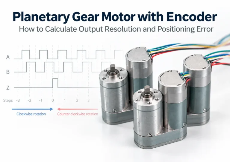
Encoder feedback cannot compensate for an unsuitable mechanical fit. Even when a planetary gear motor with an encoder is used, the supporting structure and assembly consistency must first be controlled.
Functions and Manufacturing Processes of the End Flanges
Depending on the gearbox design, an end flange may connect the motor, mount the gearbox, support a bearing or locate an axial component. The following manufacturing routes are suitable for different flange designs.
| Manufacturing Process | Common Materials | Process Characteristics and Suitable Conditions |
|---|---|---|
| Precision CNC Turning and Milling | 6061 and 7075 aluminium alloys; SUS303 and SUS304 stainless steels; brass | Turning is used for outside diameters, bores, end faces and locating pilots, while milling, drilling and tapping produce other features. Suitable for precision support parts, prototypes and customised components. Tolerances must still be confirmed from drawings and inspection results. |
| Metal Injection Molding MIM | 316L and 17-4PH stainless-steel powders; iron-based alloys | Metal powder and binder are injection molded, debound and sintered. Critical locating pilots, bearing bores and threads can be finish-machined. Suitable for complex small metal components in volume production, but tooling, shrinkage and demolding must be evaluated. See the MPIF metal injection molding guide. |
| Engineering-Plastic Injection Molding | POM; PA66 GF30 glass-fibre-reinforced nylon; PEEK | Suitable for lightweight structures, defined load requirements and volume production. Rigidity, creep, moisture absorption and operating temperature must be checked. PEEK is used for higher-performance requirements and should not automatically be treated as a low-cost material. |
| Stamping and Deep Drawing | SPCC cold-rolled steel sheet; SUS304 stainless-steel sheet | Blanking, punching, bending or drawing can produce thin-sheet flanges and end covers. Suitable for structures designed for volume production. Progressive tooling depends on geometry and production volume, while support-hole accuracy and flatness still require inspection. |
CNC machining can help control the positional relationship between related features, but the machine name alone does not guarantee a fixed tolerance or prevent binding after assembly.
The economic production volume for MIM depends on component complexity, tooling cost and secondary machining. Similarly, the use of a plastic flange does not mean that the complete gearbox can operate without lubrication.
Final inspection should confirm that the locating pilot, bearing bore, end face, threads and axial dimensions satisfy the support and assembly requirements.
Bearings and Lead-Screw Output Support
In conventional TSL Motor planetary gearbox designs, the output is generally supported by ball bearings to carry rotating components and reduce friction.
The bearing type, quantity and installation position must be selected according to the actual structure. Planet gears may use direct pin support or bushings. The presence of ball bearings at the output does not mean that each planet gear also contains a ball bearing.
For applications requiring linear motion, the output shaft can be designed as a lead screw that drives a guided nut. Push-pull loading generates an axial reaction force in the lead screw. The complete load path should therefore be checked from the lead-screw shoulder and support bearing to the flange and gearbox housing.
Radial load and overhung moment must also be evaluated. An external linear guide should carry the appropriate side load; permissible thrust cannot be determined from gearbox output torque alone.
For applications with higher axial loads, or combined radial and axial loads together with demanding support-rigidity requirements, TSL Motor may use angular contact ball bearings.
An angular contact ball bearing is still a type of ball bearing. A single-row bearing normally carries axial load primarily in one direction. A bidirectional push-pull mechanism therefore requires a suitable paired arrangement or another structure capable of supporting axial load in both directions.
Actual load capacity depends on bearing size, contact angle, preload, life requirement and bearing-seat rigidity. It cannot be determined from the term “angular contact” alone. Further design information is available in SKF’s technical guide to single-row angular contact ball bearings.
Injection Molding and Tooling for Plastic Gears
Plastic gears are generally injection molded for volume production. Molten polymer fills a mold cavity containing the gear profile and forms the component after filling, packing and cooling.
Unlike individual gear cutting, the mold performs the main tooth-profile replication. If an existing mold cannot produce a non-standard tooth count, module, bore or integrated hub, a new mold or insert may be required, or the existing tooling may need modification.
“Non-standard” does not necessarily mean that the complete mold must be rebuilt. A change to an external shaft interface may not affect the gear cavity. In contrast, even a small dimensional change may require a new trial if it affects tooth geometry, shrinkage or demolding.
Plastic blanks may be machined for early low-volume prototypes. However, the behaviour of a machined prototype cannot fully represent that of an injection-molded production part.
Important injection-molding controls include:
- Mold accuracy
- Filling
- Packing pressure
- Cooling
- Forming shrinkage
- Warpage
- Bore stability
A study on shrinkage control in micro injection-molded small-module plastic gears shows that non-linear shrinkage can affect tooth-profile accuracy. The mold cavity should therefore not be created simply by uniformly scaling the finished-part CAD model.
Production validation should also consider the selected resin’s temperature and moisture-absorption characteristics, together with the actual combination of gear material, planet pin and lubricant.
A “plastic planetary gearbox” does not mean that every component is plastic. Plastic planet gears may be combined with a metal sun gear, metal pins or a metal output stage. The material and manufacturing process of every component should be defined separately. Complete gearbox life and load capacity cannot be judged from a single material name.
Compacting and Sintering Powder-Metallurgy Gears
Powder metallurgy is a group of manufacturing technologies rather than a material category completely separate from steel. Iron-based powder-metallurgy gears may also use steel alloy systems.
This section refers to the conventional press-and-sinter route commonly used for miniature gears. MIM, listed in the flange table above, also belongs to powder metallurgy, but it introduces binder-assisted injection molding and debinding. It is not the same manufacturing process as conventional die compaction.
A typical press-and-sinter process includes:
- Powder preparation and mixing
- Compaction of the green part in a die
- Sintering
- Sizing when required
- Heat treatment or local secondary machining when required
The tooth profile can be formed close to its final geometry during compaction, so every tooth slot does not necessarily need to be cut individually as it would be in a machined steel gear.
Dimensions still change during sintering, and a sizing operation may be required to recalibrate the component. EPMA’s overview of conventional press-and-sinter manufacturing also identifies sizing as an available secondary operation.
Powder-metallurgy gears require dedicated tooling. A new tooth profile or stepped geometry affects the die and compaction method. Demolding, local density and secondary machining should therefore be evaluated during the design stage.
Final component performance depends on the powder system, density, sintering parameters and subsequent treatment. It is inaccurate to state that powder metallurgy is always low-precision or suitable only for low-torque applications.
The suitability of a powder-metallurgy gear still requires validation under the actual load and expected service life. For a broader comparison of manufacturing materials, see Micro Planetary Gear Motor Selection: Steel vs. PM vs. POM.
10. How the Three Manufacturing Routes Affect Product Development
| Manufacturing Route | How the Gear Teeth Are Formed | Non-Standard Development Focus | Volume-Production Inspection Focus |
|---|---|---|---|
| Machined Steel Gear | External teeth may be hobbed; internal teeth may be shaped, power-skived, broached or wire-cut according to the structure | Gear blank, cutting tool, machining program, fixture and heat-treatment route; machining does not mean zero tooling cost | Tooth profile and pitch, runout, fit dimensions and distortion after heat treatment |
| Plastic Injection Molding | The mold cavity replicates the tooth profile before the part cools and is ejected | New mold or insert, shrinkage compensation, gate design and mold trials; machined prototypes may be evaluated during early development | Tooth profile, shrinkage, warpage, bore size and batch consistency |
| Powder Compaction and Sintering | The die forms a near-net-shape gear, which can later be sized or locally machined | Powder system, die design, demolding, density and dimensional change during sintering | Density, dimensions, tooth geometry, mechanical properties and required secondary-machining results |
A meaningful cost comparison must include prototypes, cutting tools or molds, individual machining, secondary processing and inspection. Comparing only the quoted unit price gives an incomplete picture.
An existing product configuration can be reviewed through the TSL-28GAY-385 28 mm planetary gear motor, but the manufacturing route of one product series should not be generalized to every gearbox size.
Component Manufacturing Must Be Followed by Assembly Validation
Components that meet their individual dimensional requirements do not automatically guarantee the performance of the assembled gearbox.
The location of the ring gear in the housing, the carrier hole pattern, planet-pin fits, bearing seats, axial clearance and lubrication condition all affect the final assembly. Machining accuracy is only the foundation. Backlash, no-load drag, noise and temperature rise must still be measured under defined conditions.
Machining accuracy is only the foundation. Actual backlash, no-load resistance, noise and temperature rise must still be measured under defined conditions. For related validation methods, see How Does Planetary Gearbox Backlash Affect Positioning Accuracy?.
An appropriate acceptance plan may include:
- Component dimensional inspection
- Gear-profile and pitch inspection
- Rotation checks after assembly
- Backlash measurement
- No-load drag measurement
- Noise and temperature-rise testing
- Operation under the specified load and duty cycle
- Durability testing when required
A lead-screw output should also be tested for push-pull reversal, axial movement, bearing preload and temperature rise under load.
If motor current is used to evaluate assembly resistance, the motor model, voltage, speed, temperature and lubrication conditions must all be controlled. A single no-load current reading should not be treated as proof of gearbox efficiency or service life.
Conclusion
Planetary gearbox manufacturing requires control of both gear geometry and supporting structures. In the TSL Motor steel-geared design described here, the sun and planet gears receive hobbed external teeth, the carrier and planet pins are CNC machined, and selected ring gears with demanding profile requirements are manufactured by precision wire EDM.
The end flanges and bearings establish location and support. A lead-screw output additionally requires a bearing arrangement matched to the axial and radial loads. A deviation in any one of these areas can appear after assembly as uneven load distribution, excessive friction, noise or abnormal wear.
When plastic or powder-metallurgy gears are used, tooling, forming variation and downstream inspection must be evaluated again rather than simply replacing the material name on an existing drawing.
The design process should first establish load, available space, expected life and production volume. It can then determine which surfaces require finish machining, which dimensions need tighter control and which tests are required to validate final performance.
If your project requires modifications to the gear structure, planet carrier, planet pins, lead-screw output or mounting interface, please contact the TSL Motor engineering team with the available diameter and length, target ratio, output speed, rated and peak torque, axial and radial loads, duty cycle, installation drawing and estimated order quantity.
FAQ
Are All Steel Components in a Planetary Gearbox Manufactured by Hobbing?
No. Hobbing is used to produce suitable gear teeth, such as the external teeth of the sun and planet gears in the design described here. Carriers, pins and flanges are generally turned, milled, drilled or bored according to their geometry. Internal ring gears require a manufacturing route specifically suited to internal teeth.
Can Wire EDM Produce a Zero-Backlash Ring Gear?
No. Wire EDM controls only the profiles and dimensions produced by that operation. Complete-gearbox backlash is also affected by the sun gear, planet gears, pins, carrier, support structure and assembly clearances.
Wire EDM is not automatically superior to every shaping or power-skiving process. The appropriate route should be selected according to component requirements and assembled-gearbox acceptance criteria.
Why Might a Lead-Screw Output Require Angular Contact Ball Bearings?
Push-pull loading on a lead screw creates an axial reaction force and may also introduce radial loading. Angular contact ball bearings can support this combination of loads, but bidirectional movement requires a suitable bearing orientation, paired arrangement or another appropriate support structure.
Permissible load must still be calculated from the specific bearing parameters and complete mechanical design.
Do Non-Standard Plastic and Powder-Metallurgy Gears Require New Tooling?
For volume production, new tooling, inserts or tooling modifications are normally required if the new geometry cannot be produced by the existing tools.
Plastic gears require evaluation of injection molding, shrinkage and demolding. Powder-metallurgy gears require evaluation of compaction, density and part ejection. Alternative machining routes may be used for prototypes, but prototype manufacturing should not be confused with the final volume-production process.
Can the Manufacturing Process of a Flange Be Identified from Its Appearance?
Not reliably. Turning marks, parting lines or stamping traces may provide clues, but they can be removed or covered by secondary machining and surface treatment.
Reliable identification should be based on the specified material, engineering drawing, supplier process information and inspection results. A round flange may also be manufactured from a formed blank and then finish-machined by CNC.