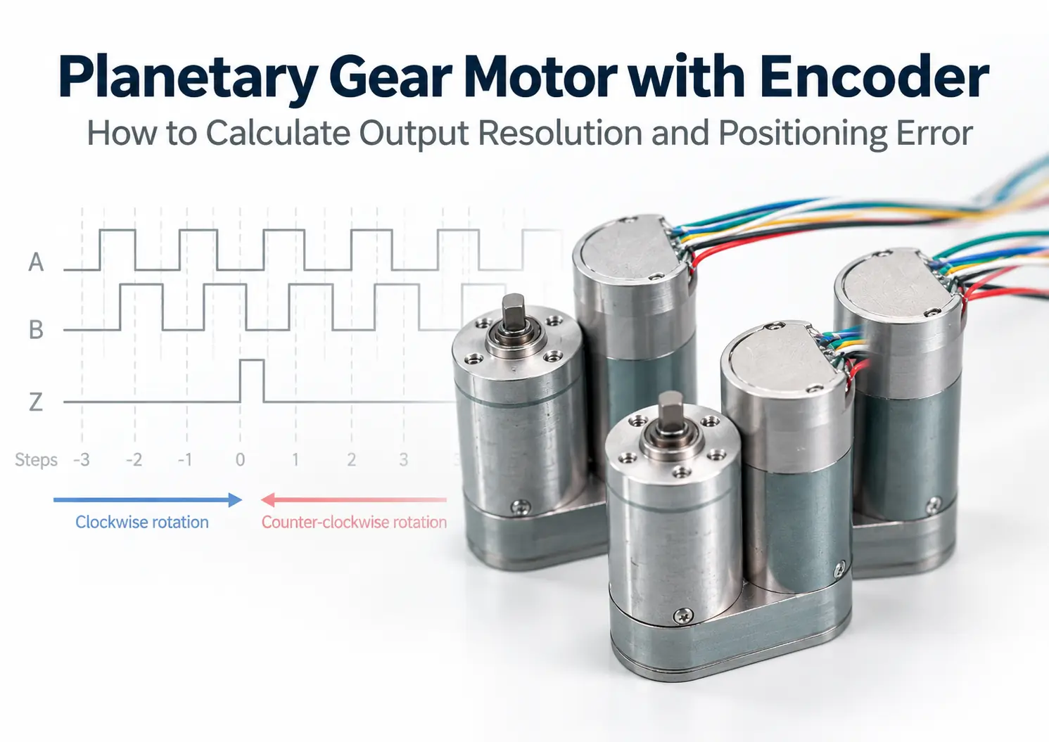

When comparing 11 PPR with 16-bit, 11 PPR seems to have very low resolution, while 16-bit appears precise enough. However, no component in any equipment should be discussed in isolation. The three key practical questions are: how the controller actually counts, whether the encoder is installed before or after the gearbox, and how much mechanical backlash exists when the output shaft reverses.
For example, an 11 PPR encoder paired with a 100:1 gearbox provides 1,100 counts per output shaft revolution under x1 counting. A 16-bit motor-side absolute encoder paired with an 8:1 gearbox can theoretically be converted to 524,288 position increments per output shaft revolution.
A planetary gear motor with an encoder must be analyzed by combining the electronic measurement chain and the mechanical transmission chain: Encoder Resolution → Controller Decoding Mode → Actual Gear Ratio → Encoder Installation Location → Gearbox Backlash & Transmission Error → Load-Side Position
The true question to answer is not “how many PPR or bits does the encoder have,” but rather: with what margin of error can the output shaft reach the target position under real loads, reverse rotation, and temperature rise conditions?
Key Takeaways
- PPR or bit depth describes measurement granularity and does not directly represent positioning accuracy.
- PPR, CPR, and x1/x2/x4 decoding must be verified according to the encoder and controller specifications.
- The theoretical output resolution of a motor-side encoder increases with the gear ratio, but it cannot reflect any mechanical errors downstream of the gearbox.
- An output-side encoder directly measures the load-side angle, so its resolution cannot be multiplied by the gear ratio again.
- A single-turn motor-side absolute encoder cannot uniquely determine the complete absolute angle of the output shaft on its own.
- Backlash mainly surfaces when the direction of motion or load changes; high-resolution encoders cannot physically eliminate gear teeth clearance.
- The selection order should always start with determining the allowable output error, followed by selecting the gearbox, feedback location, and encoder resolution.
Distinguishing Resolution, Accuracy, Backlash, and Positioning Error
These parameters are often listed in the same spec sheet, but they address entirely different questions.
| Parameter | Question It Actually Answers |
| Encoder Resolution | How many theoretical positions or counts divide one full revolution? |
| Encoder Accuracy | What is the deviation between the position reported by the encoder and the actual shaft angle? |
| Quantization Error | What is the minimum reading uncertainty caused by discrete counting? |
| Gearbox Backlash | How much mechanical lost motion exists at the output end after reversing or torque reversal? |
| Transmission Error | What is the periodic or cumulative deviation between the input and ideal transmission ratio? |
| Torsional Stiffness | How much elastic twist occurs in the drive system under load torque? |
| Repeatability | How consistent are the results when executing the same movement multiple times? |
| System Positioning Accuracy | How far is the final load position from the commanded position? |
Therefore, a 16-bit encoder can provide 65,536 theoretical positions, but the actual system accuracy may still be limited by the intrinsic encoder accuracy, mounting eccentricity, magnet air gap, shaft runout, gearbox backlash, structural deformation, and control tracking error.
Incremental Encoders: Defining PPR, CPR, and Decoding Modes First
Incremental encoders typically output A and B phase signals, with some models including an index Z signal once per revolution. The A and B phases differ by 90° electrical phase, allowing the controller to determine direction and count edges in different modes.
However, terminology like PPR and CPR varies across manufacturers. Some define PPR as base pulses per revolution per channel, while others refer to the quad-edge count as PPR. For example, official specifications for US Digital E5 encoders state 32–5,000 CPR and 128–20,000 PPR within the same series, differing by a factor of 4. Always consult the specific datasheet before running calculations.
To eliminate ambiguity, this guide defines:
- P:Base pulses per revolution for a single channel
- k:Controller decoding multiplier (1, 2, or 4)
- i:Actual gear ratio of the gearbox
- C_out:Controller counts per output shaft revolution
Counts Per Output Shaft Revolution:
C_out = P × k × i
Theoretical Output Angular Resolution:
θ_step = 360° ÷ C_out
11 PPR Encoder with a 100:1 Gearbox Example (e.g., TSL-24GAY-370-EN configuration with 11 PPR base resolution and 100:1 ratio):
| Decoding Mode | Counts per Motor Rev | Counts per Output Rev | Theoretical Output Angle / Count |
| x1 | 11 | 1,100 | 0.3273° |
| x2 | 22 | 2,200 | 0.1636° |
| x4 | 44 | 4,400 | 0.08182° |
“11 PPR × 100 = 1,100” only holds true when counting base pulses under x1 mode. If using x4 quadrature decoding, the system theoretically yields 4,400 counts per output revolution.
In engineering specs, write:
11 PPR motor-side AB encoder; 4,400 counts per output revolution at 100:1 with x4 decoding.
This description is much less likely to be misunderstood than simply stating “11 PPR.” Different feedback configurations can also be compared through the available motor encoder options.
How Gear Ratio Affects Theoretical Output Resolution
When an encoder is installed on the motor shaft, the motor rotates several times for every revolution of the gearbox output. The reduction ratio therefore increases the theoretical output-equivalent resolution.
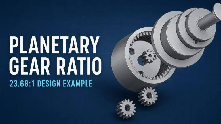
However, the calculation should use the actual ratio generated by the gear tooth combination, not only the rounded catalog ratio.
If a gearbox is described as 100:1 but its actual ratio is not exactly 100.000:1, cumulative position and speed calculations can gradually drift. The difference may be insignificant in a short-stroke relative positioning system, but it becomes more important when tracking accumulated revolutions, synchronizing multiple axes or integrating speed over long operating periods.
The more accurate calculation is:
C_out = P × k × i_actual
The gear ratio improves the theoretical measurement granularity after conversion to the output shaft. It does not improve backlash, transmission error or output stiffness by the same proportion.
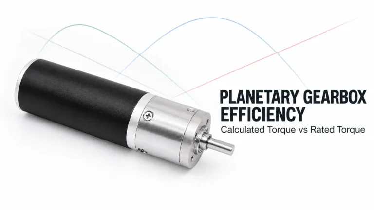
Additional gearbox stages may also introduce more efficiency losses and more sources of mechanical error. For a detailed explanation of stage efficiency and usable output capability, see Planetary Gearbox Efficiency: Calculated vs Rated Torque.
Absolute Encoders: Bit Depth Is Not Absolute Accuracy
The theoretical number of positions provided by an n-bit single-turn absolute encoder is:
N = 2ⁿ
The theoretical angle represented by each position is:
θ_encoder = 360° ÷ 2ⁿ
For example:
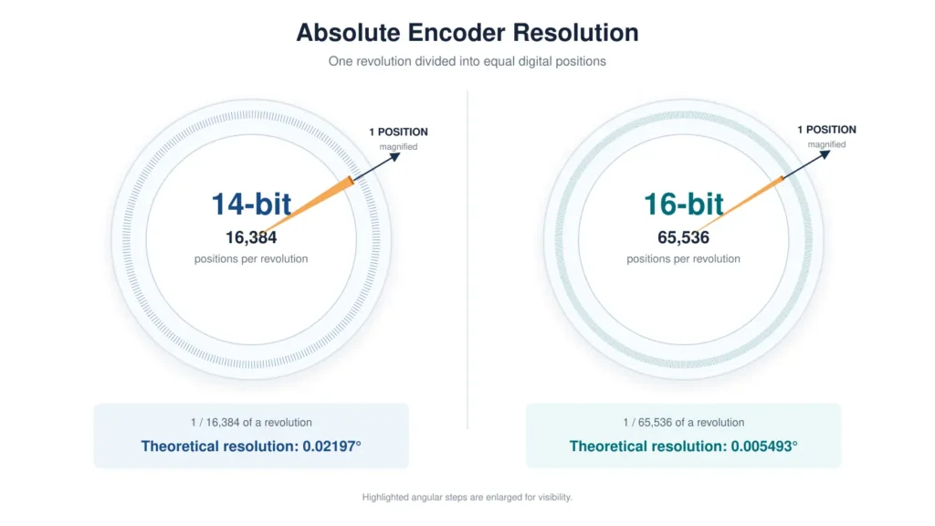
- 14-bit = 16,384 positions, with a theoretical step of approximately 0.02197°
- 16-bit = 65,536 positions, with a theoretical step of approximately 0.005493°
The official Baumer EFL580 datasheet defines 13-bit resolution as 8,192 steps per revolution, clearly illustrating the relationship between bit depth and theoretical position count.
Bit depth alone, however, does not specify absolute accuracy, linearity error, repeatability or mounting error.
If a 16-bit encoder is mounted on the motor shaft and the reduction ratio is i, the theoretical output-equivalent step is:
θ_output_equivalent = 360° ÷ (65,536 × i)
The term “output-equivalent” is important. This value is obtained by converting the motor-side digital increment through the gear ratio. It does not mean that the encoder has directly measured the gearbox output shaft.
A Commonly Overlooked Limitation of Single-Turn Motor-Side Encoders
Assume that a gearbox has an 8:1 ratio. The motor-side encoder completes eight electrical position cycles while the output shaft completes one revolution.
A single-turn absolute encoder can report the motor shaft position within its current 0–360° revolution, but a single data frame cannot identify which of the eight motor revolutions corresponds to the current output position.
To determine the complete output angle, the system needs at least one of the following:
- The controller continuously stores the motor revolution count
- The mechanism performs a homing operation after power-up
- A multiturn absolute encoder is used
- Absolute position feedback is installed on the gearbox output
The control architecture must also define whether the revolution count is retained after power loss, whether the load can back-drive the motor and whether the mechanism has physical travel limits.
Encoder Location Often Matters More Than Additional Bit Depth
| Feedback Location | Main Advantages | Errors It Cannot Directly Observe or Separate |
|---|---|---|
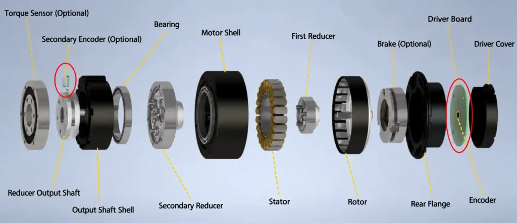
| Motor-side encoder | High feedback frequency; suitable for commutation, speed control and fast motor loops; very fine theoretical output-equivalent resolution after applying the gear ratio | Gearbox backlash, output connection clearance and load-side elastic deformation |
| Output-side encoder | Directly measures the actual angle after the gearbox; suitable for joint and load-side positioning | When used alone, it may not identify whether an error originates from the motor, gears or output connection |
| Motor-side and output-side dual encoders | Observe both motor motion and load response; support dual-loop control, backlash identification and fault monitoring | Cannot physically eliminate gear clearance and requires more complex controller tuning |
An output-side encoder is already measuring the gearbox output shaft. Its resolution must therefore not be multiplied by the gear ratio again.
The theoretical step of a 16-bit output encoder is simply:
360° ÷ 65,536 = 0.005493°
Dividing this value by the gear ratio again would produce an attractive but physically meaningless number.
TSL-GIM6010-8 Example: Comparing 16-Bit Resolution with 15 Arcmin Backlash
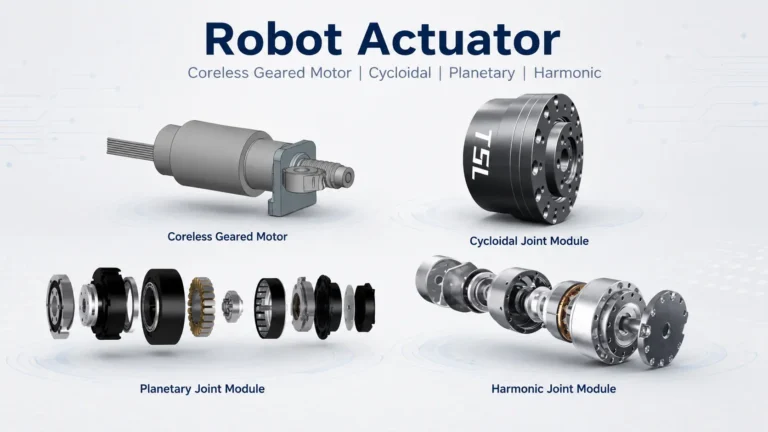
The TSL-GIM6010-8 planetary robot joint module uses an 8:1 planetary gearbox with a 16-bit motor-side encoder and an optional secondary encoder.
Its specified gearbox backlash of 15 arcmin provides a useful example of the difference between digital resolution and mechanical positioning capability.
Motor-Side 16-Bit Encoder
The theoretical motor-side step is:
360° ÷ 65,536 = 0.005493°
Converted through the 8:1 gearbox:
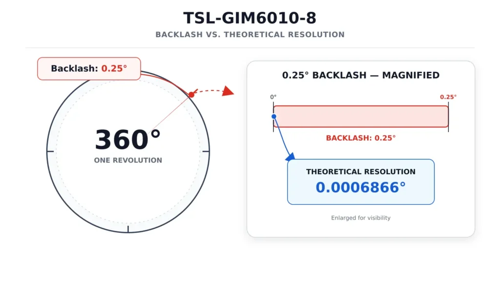
0.005493° ÷ 8 = 0.0006866°
This is approximately 0.0412 arcmin, or 2.47 arcsec.
Comparison with Gearbox Backlash
Fifteen arcminutes equals 0.25°.
0.25° ÷ 0.0006866° ≈ 364
The specified gearbox backlash is therefore approximately 364 times larger than the theoretical motor-side encoder step converted to the gearbox output.
This does not mean that the positioning error equals 364 encoder counts. It shows that once the motor-side measurement increment is already much smaller than the mechanical lost motion, increasing the motor-side bit depth further is unlikely to be the first priority for improving bidirectional output positioning.
If a second 16-bit encoder is installed directly on the output shaft, its theoretical step remains 0.005493°. The 15 arcmin backlash is still approximately 45.5 times larger than this step.
Although the output encoder has a coarser numerical step than the motor-side output-equivalent value, it can detect whether the actual output shaft has started moving. That is its main advantage.
What Can Output Feedback Correct—and What Can It Not Correct?
When the motor reverses, the motor-side encoder may already report movement while the gears are still crossing the backlash deadband and the output shaft remains stationary.
The NIST study on robot joint degradation describes this process clearly: during reversal, the gear teeth first disengage, the output remains stationary until the opposite tooth flanks make contact, and the new engagement may introduce changes in velocity and torque.
An output-side encoder allows the controller to detect that the motor has moved while the load has not. The controller can then continue correcting the final position within the permitted speed and torque limits.
Dual motor-side and output-side feedback can also support:
- A fast inner motor-speed loop and a slower load-position loop
- Identification of direction-dependent position offsets
- Monitoring of gearbox wear or output connection looseness
- Improved joint position holding under external disturbances
However, output feedback cannot turn a gearbox with clearance into a zero-backlash mechanism. The reversal deadband, tooth re-engagement impact and contact-stiffness variation still exist.
If controller gains are too high, the system may repeatedly search for opposite tooth flanks and begin oscillating. A dual-encoder system is therefore not only a sensor-selection issue; it also affects mechanical design and control-loop bandwidth allocation.
In a multi-DOF dexterous hand, joint-sensor concentricity, magnet air gap and whole-hand calibration must also be considered. For a related design discussion, see Optimizing MCP Joint Angle Sensors in Micro Dexterous Hands.
Why Can Small Planetary Gearboxes Still Have 2–3° of Backlash Despite High Encoder Resolution?
Based on TSL Motor’s experience with mass-produced micro planetary gearboxes, output backlash of approximately 2–3° is not unusual in some platforms with diameters of 16 mm or smaller, particularly when they use multiple stages, conventional tooth profiles and normal commercial cost targets.
This is not a fixed value for every miniature planetary gearbox and should never replace model-specific test data. Gear material, module, number of stages, pin fit, bearing support, test torque, temperature and wear condition can all affect the result.
The size-related difficulty can be understood through a simple geometric relationship:
Angular error in radians ≈ Circumferential clearance ÷ Effective radius
Assume that the equivalent circumferential clearance is 10 μm:
- At an effective radius of 3 mm, the angular error is approximately 0.191°
- At an effective radius of 15 mm, the angular error is approximately 0.0382°
The same linear manufacturing deviation creates a larger angular error at a smaller radius.
Miniature gears must also retain enough clearance for lubrication, thermal expansion and assembly tolerance. Backlash cannot be reduced indefinitely by simply minimizing tooth-side clearance.
This is why the TSL-16GP-EC1636 coreless brushless planetary gear motor still requires a separate gearbox-backlash evaluation even though its coreless motor provides low rotor inertia and Hall feedback.
Additional sizes and reduction ratios can be compared in the planetary gear motor product range.
Why Is Angular Backlash Easier to Control in Larger-Diameter Joint Modules?
A larger gear pitch radius converts the same linear manufacturing deviation into a smaller angular error. It also provides more space for precision gear machining, stronger bearing support and a stiffer planet carrier.
However, a larger diameter does not automatically create a low-backlash gearbox. Gear accuracy, material, heat treatment, supporting structure and assembly process still determine the final result.
The TSL-GIM4315-40 planetary robot joint module provides an example that is closer to a high-torque robotic joint.
| Parameter | Value |
|---|---|
| Reduction ratio | 40:1 |
| Gear material | Steel |
| Gearbox backlash | 15 arcmin |
| Integrated encoder | 14-bit |
| Secondary output encoder | Supported |
| Rated torque | 15.50 N·m |
| Peak torque | 45.41 N·m |
A 14-bit encoder has a theoretical motor-side step of approximately 0.02197°. If it is installed on the motor and ideally converted through the 40:1 reduction ratio, the theoretical output-equivalent step becomes approximately 0.000549°—still much smaller than the 0.25° mechanical backlash.
This again demonstrates that fine digital feedback is beneficial for motor control, but bidirectional load positioning must still be evaluated according to output feedback, backlash, stiffness and test conditions.
How to Build a Realistic Output Positioning Error Budget
The positioning error of a planetary gear actuator cannot be represented by a single encoder equation. A practical error budget should consider at least the following sources:
E_total = Encoder error + Mounting error + Transmission error + Backlash effect + Elastic deformation + Control tracking error + Thermal drift
This is an engineering checklist, not a rule that every error must always be added linearly.
- Backlash is a direction-dependent dead zone and is normally specified as a total bidirectional value or under a defined reversing torque
- Torsional deformation changes with load torque and is not a fixed constant
- Ideal encoder quantization error is approximately ± half of one theoretical step
- Periodic transmission error may change with the gearbox output angle
- An output-side closed loop can correct some measurable static mechanical offsets, but it cannot eliminate dynamic deadband or structural deformation
For a conservative worst-case estimate, errors that may reach their maximum in the same direction can be added by absolute value.
A root-sum-square method is more appropriate only when the errors are statistically independent, approximately random and supported by a valid statistical model.
A formal specification should always state the measurement temperature, load, reversing torque, speed, mounting conditions and evaluation method.
Converting Angular Error into Load-Side Linear Displacement
For a small angle:
Linear displacement ≈ Effective radius × Angle in radians
For example, 15 arcmin equals 0.25°, or approximately 0.004363 rad.
If the effective load radius is 150 mm, the theoretical bidirectional geometric difference corresponding to the backlash is:
150 mm × 0.004363 ≈ 0.654 mm
This does not mean that the mechanism will always produce a one-sided error of 0.654 mm. The actual position depends on tooth-loading direction, gravity, friction and control strategy.
The calculation is still useful because it quickly shows whether a specified backlash level could satisfy the required end-point tolerance.
How to Select Among Three Common Feedback Architectures
| Feedback Architecture | Theoretical Output Resolution | Absolute Position at Power-Up | Direct Output-Angle Measurement | Suitable Applications |
|---|---|---|---|---|
| Motor-side incremental encoder | P × k × i counts per output revolution | Normally requires homing | No | Speed control, cost-sensitive systems and actuators that can perform homing |
| Motor-side single-turn absolute encoder | Output-equivalent step of 360° ÷ (2ⁿ × i) | Directly identifies only the motor’s single-turn position | No | BLDC commutation, fast inner loops and limited-travel joints with revolution tracking |
| Output-side absolute encoder | 360° ÷ 2ⁿ | Yes | Yes | Robot joints, valves, gimbals and bidirectional load positioning |
| Motor-side and output-side dual encoders | Each encoder’s resolution is calculated separately | Depends on the output encoder type | Yes | High-accuracy joints, externally disturbed systems and condition-monitoring applications |
For basic speed and direction feedback on an existing miniature gear motor, a motor-side incremental encoder is often sufficient.
If the system must know the joint angle immediately after power-up, or if the load frequently reverses, output-side absolute feedback deserves higher priority.
A More Reliable Selection and Validation Process
Step 1: Begin with the Load-Side Error Requirement
Define the allowable angular error or linear displacement, the effective load radius, whether positioning is unidirectional or bidirectional, and how frequently the mechanism reverses.
Do not begin with the statement, “We need a 16-bit encoder.”
Step 2: Establish the Mechanical Error Budget
Allocate separate limits for gearbox backlash, structural deformation, bearing clearance and assembly error.
Ask the supplier whether the stated backlash is a total or one-sided value, and confirm the test torque and temperature.
Step 3: Select the Feedback Location
Motor commutation and high-speed inner loops require motor-side feedback. Actual load angle requires output-side feedback.
If both are necessary, evaluate a dual-encoder architecture.
Step 4: Calculate the Required Resolution
Use the confirmed PPR, decoding multiplier, bit depth and actual gear ratio to calculate the theoretical step.
The theoretical step should be clearly smaller than the error budget assigned to the sensor. Excessive resolution without sufficient accuracy, stiffness or signal quality only increases data volume and control complexity.
Step 5: Check Electrical and Dynamic Limits
At maximum motor speed, the encoder pulse frequency must remain within the output capability of the encoder and the input capability of the controller.
Communication cycle time, sampling delay, noise, cable length, power supply and revolution-count retention after power loss must also be checked.
Step 6: Test the Complete Mechanism
Test at multiple output angles, in both directions, under different loads and temperatures, and repeat the measurement after running-in.
For a dexterous hand or multi-joint robot, final validation must include end-effector positioning and multi-axis coupling calibration—not only isolated actuator testing.
For projects requiring a customized diameter, reduction ratio, feedback architecture or output interface, begin by defining the allowable error, rated and peak torque, speed, duty cycle and available installation space. These requirements can then be compared against a 16 mm planetary gear motor example or the broader planetary gear motor range.
Common Calculation Errors
| Common Error | Why It Is Incorrect |
|---|---|
| Stating PPR without specifying x1, x2 or x4 decoding | The final count can differ by a factor of four |
| Mixing PPR with the controller’s final CPR value | Encoder manufacturers do not use these terms consistently |
| Using a rounded catalog ratio for precision accumulated-position calculations | The catalog ratio may have been rounded |
| Treating a 16-bit encoder as providing ±0.005493° accuracy | This is the theoretical step, not absolute accuracy |
| Multiplying motor-side encoder resolution by the gear ratio and calling it output accuracy | Gearbox errors occur after the feedback point |
| Applying the gear ratio again to an output-side encoder | The output encoder already measures the output shaft |
| Assuming that higher PPR eliminates backlash | An encoder does not change the physical gear clearance |
| Using unidirectional repeatability as bidirectional accuracy | Backlash becomes most visible during reversal |
| Testing only at no load and at one angular position | Load, gear position and temperature can all change the result |
FAQ
How Is the Output Resolution of a Planetary Gear Motor Calculated?
If an incremental encoder is mounted on the motor shaft:
Counts per output revolution = Base PPR × Decoding multiplier × Actual gear ratio
The theoretical angular resolution is:
360° ÷ Counts per output revolution
Before calculating, confirm whether the manufacturer’s PPR value already includes quadrature decoding.
Does a 16-Bit Motor-Side Encoder Become More Accurate After the Gearbox?
Its theoretical output-equivalent step becomes smaller according to the reduction ratio, but actual positioning accuracy does not automatically improve by the same proportion.
Backlash, transmission error, torsional deformation and output connection clearance still occur after the motor-side encoder.
Why Is the Gear Ratio Not Applied to an Output-Side Encoder?
Because the encoder already rotates directly with the gearbox output shaft.
A 16-bit output encoder provides 65,536 theoretical positions per output revolution, corresponding to a step of approximately 0.005493°. Dividing this value by the gear ratio again would count the reduction twice.
Can an Output Encoder Eliminate Planetary Gearbox Backlash?
No. It can allow the controller to observe the actual output position and compensate for some repeatable static offset, but it cannot eliminate gear clearance, tooth re-engagement impact or load-dependent elastic deformation.
When Is a Dual-Encoder System Worth Using?
A dual-encoder system is valuable when the application needs both fast motor control and accurate load-side position feedback, or when it must identify backlash, wear and external disturbances.
For a unidirectional speed-control application or a mechanism that can perform homing, a single motor-side encoder is usually more economical.
Conclusion
A planetary gear motor with an encoder should not be selected from PPR or bit depth alone.
The theoretical output resolution of a motor-side incremental encoder depends on its base PPR, the controller’s decoding method and the actual reduction ratio. A motor-side absolute encoder can also be converted through the gear ratio, but the resulting value remains an output-equivalent measurement increment—not a direct measurement of the gearbox output.
The TSL-GIM6010-8 example makes the difference clear. Its 16-bit motor-side encoder combined with an 8:1 gearbox provides a theoretical output-equivalent step of approximately 0.0006866°, while the gearbox backlash is 15 arcmin, or 0.25°.
The electronic resolution is already much finer than the mechanical lost motion that appears during reversal. In this situation, increasing bit depth alone offers limited benefit. Controlling backlash and stiffness—and deciding whether the load requires output-side feedback—becomes more important.
A more reliable engineering sequence is:
Define the allowable load-side error → Allocate the mechanical error budget → Select the encoder location → Calculate the required PPR or bit depth → Verify electrical and dynamic limits → Perform bidirectional testing under load on the complete mechanism.