

The basic formula for planetary gear reduction ratios seems straightforward: count the teeth on the sun gear and ring gear, plug them in, and you get the transmission ratio.
In real-world gearbox selection, however, this number is just the starting point. Even if a specific set of gear teeth yields the target reduction ratio mathematically, it may fail to satisfy center-distance requirements or planetary gear spacing rules.
Furthermore, even if the theoretical output torque seems sufficient, it may exceed the gearbox’s allowable continuous mechanical torque once efficiency losses, temperature rise, bearing loads, and service life requirements are factored in.
Engineers comparing available diameters, motor types and reduction ratios can review our planetary gear motor range.
Key Takeaways
- For a fixed-ring planetary gearbox with sun-gear input and planet-carrier output, the ratio is i = 1 + (Zr / Zs).
- Planet-gear tooth count does not directly enter the ratio formula, but it affects center distance and assembly feasibility.
- For a standard, unshifted planetary set with a common module, the basic geometry condition is Zr = Zs + 2 × Zp.
- Module affects pitch diameter, tooth size and packaging, but it does not directly determine the reduction ratio.
- The total ratio of a multi-stage planetary gearbox is the product of the individual stage ratios.
- In the TSL Motor example, a 5.4:1 first stage and an approximately 4.385:1 second stage produce a total ratio of approximately 23.68:1.
What Determines the Planetary Reduction Ratio?
A typical simple planetary gearbox consists of a sun gear, planet gears, an internal ring gear, and a planet carrier. This article focuses on the most common configuration used in micro planetary gear motors:
• Sun Gear: Input
• Ring Gear: Fixed
• Planet Carrier: Output
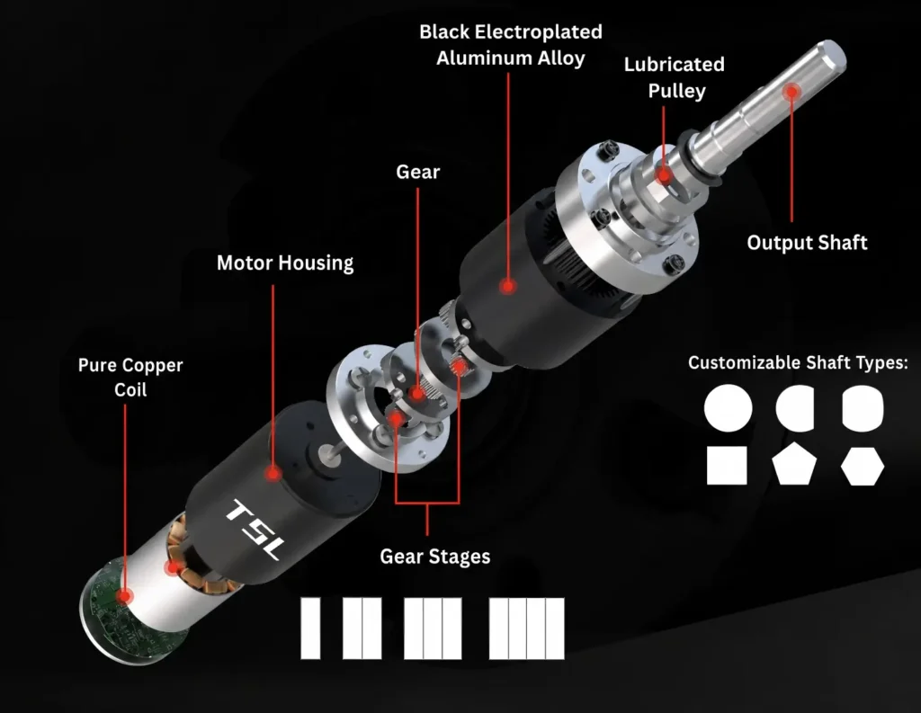
The motor drives the central sun gear. The planet gears mesh simultaneously with the sun gear and the stationary ring gear. Because the ring gear cannot rotate, the planet gears orbit around the sun gear while revolving on their own axes. The pins of the planet gears are mounted on a shared planet carrier, which ultimately drives the central output shaft.
PLANETARY GEARBOX GEAR RATIO FORMULA:
i = 1 + (Zr / Zs)
Where Zr is the number of teeth on the ring gear, and Zs is the number of teeth on the sun gear
Important Note: The number of planet gears does not directly alter this reduction ratio. Given identical sun and ring gear tooth counts and the same kinematic structure, three planet gears or four planet gears yield the exact same speed ratio. The number of planet gears primarily affects load sharing, spatial layout, pin forces, and structural rigidity.
How Are the Tooth Counts Designed for the Sun, Planet, and Ring Gears?
This is where a simple online ratio calculator usually stops being sufficient. For a standard simple planetary set with a common module and no modified working center distance, the tooth counts must satisfy:
CENTER DISTANCE COMPATIBILITY FORMULA
Zr = Zs + 2 * Zp
Where Zp is the number of teeth on the planet gear.
This stems from basic geometric relationships: the center distance from the sun gear to a planet gear must equal the center distance from the planet gear to the ring gear.According to the pitch diameter formula:
d = m * Z
a_sp = (m * (Zs + Zp)) / 2 = (m * (Zr - Zp)) / 2 = a_prCanceling terms yields Zr = Zs + 2 * Zp.
This relationship applies to a standard gear system. Profile-shifted gears can use a different tooth combination, but the actual working center distances of the sun-planet and planet-ring meshes must still be compatible.
The ratio equation determines how the gears move; the geometry determines whether the gears can be assembled and mesh correctly.
What Does Module Control in a Planetary Gearbox?
Module is often discussed together with gear ratio, but the two parameters perform different functions. For a standard gear,
d = m * Z
Where d is the pitch diameter, m is the module, and Z is the tooth count.
For a 44-tooth ring gear with a module of 0.3:
d_r = 0.3 * 44 = 13.2 mm
For a gearbox with a target outside diameter of approximately 16 mm, a 13.2 mm ring reference diameter is compatible with the package at an order-of-magnitude level. The remaining 2.8 mm must not be interpreted directly as housing-wall allowance: internal-gear root diameter, tooth depth, housing structure, tolerances, and manufacturing requirements must also be considered.
A larger module generally provides larger teeth and potentially greater tooth strength, but fewer teeth fit within a fixed gearbox diameter. A smaller module can provide more tooth-count options and ratio flexibility, while placing greater demands on tooth-section strength and manufacturing accuracy.
In practice, module balances:
Gearbox diameter ↔ tooth size ↔ tooth count ↔ strength ↔ achievable ratio
Module alone does not determine gearbox performance. Gear material and manufacturing method also affect tooth strength, noise, wear and production cost. For a more detailed comparison, see our guide to steel, powder-metallurgy and POM gears.
TSL Motor Example: Why Is Stage 1 Equal to 5.4:1?
The verified internal specifications for the first stage of the TSL Motor Ø16 mm planetary gearbox are as follows:
| Parameter | First Stage Value |
| Ring Gear (Zr) | 44T |
| Sun Gear (Zs) | 10T |
| Planet Gear (Zp) | 17T |
| Number of Planet Gears (N) | 3 |
| Module (m) | 0.3 |
First, verify the standard geometry relationship:
Zs + 2 * Zp = 10 + 2 * 17 = 44 = Zr
Pitch diameters for each gear:
• Sun Gear: d_s = 0.3 * 10 = 3.0 mm
• Planet Gear: d_p = 0.3 * 17 = 5.1 mm
• Ring Gear: d_r = 0.3 * 44 = 13.2 mm
Sun–Planet center distance: a_sp = (3 .0 + 5.1) / 2 = 4.05 mm Planet–Ring center distance: a_pr = (13 .2 – 5.1) / 2 = 4.05 mm Both center distances match perfectly. Therefore, 10T Sun + 17T Planet + 44T Ring satisfies standard reference geometric relationships.
A comparable 16 mm product platform is the TSL-PG16-KS1625 coreless brushed planetary gear motor. Its published ratios and torque ratings are model-specific and should not be inferred directly from this tooth-count example.
Why Can Three Planet Gears Be Spaced at 120°?
In addition to center-distance compatibility, tooth counts must fulfill planetary assembly conditions. For N equally spaced planet gears, a standard assembly rule is:
EQUIDISTANT ASSEMBLY RULE
(Zs + Zr) / N = Integer
For the first stage utilizing three planet gears:
(10 + 44) / 3 = 54 / 3 = 18
Because the result is an integer, the three planet gears can be symmetrically arranged at 120° intervals under this standard assembly condition.
How Is the First-Stage Ratio of 5.4:1 Calculated?
With the geometry verified, the first-stage ratio is:
i_1 = 1 + (44 / 10) = 5.4
The three planet gears do not multiply this ratio by three. Multiple planets create parallel torque-transmission paths, but they do not triple the speed reduction.
Their main benefit is load sharing. In an actual gearbox, however, three planets may not each carry exactly one-third of the load. Carrier pin-position error, gear runout, and tooth-thickness variation can shift the load distribution. This is why carrier accuracy and gear manufacturing quality matter in a high-performance planetary gearbox.
The ratio changes when a different planetary member is fixed, used as the input or used as the output. KHK’s gear-system reference illustrates these configuration-dependent relationships.
Why Does the Second Stage Use a 13-Tooth Sun?
With the first stage confirmed at 5.4:1 and a target total reduction ratio of 23.68:1, the theoretical second-stage ratio required is:
i_2 = 23.68 / 5.4 ≈ 4.3852
If the second stage retains a 44-tooth ring gear:
i_2 = 1 + (44 / Z_s2) ≈ 4.3852 ==> 44 / Z_s2 ≈ 3.3852
Z_s2 = 44 / 3.3852 ≈ 12.998
The nearest integer tooth count is 13. Using a 13-tooth sun gear:
i_2 = 1 + (44 / 13) ≈ 4.384615
The resulting two-stage total reduction ratio becomes
i_total = 5.4 * (1 + 44 / 13) = 5.4 * 4.384615 ≈ 23.6769 ≈ 23.68
Why Not Use the Same Sun Gear in Both Stages?
Using a 10-tooth sun in both stages would give:
i_total = 5.4 * 5.4 = 29 .16:1
Using a 13-tooth sun in both stages would give:
4.3846 * 4.3846 ≈ 19 .22:1
Neither result is close enough to the target. The mixed combination gives:
i_total = 5.4 * 4.3846 ≈ 23 .68:1
A gearbox designer therefore selects a practical combination of stage ratios based on target ratio, available diameter, feasible tooth counts, tooth geometry, and assembly conditions. The two stages do not need to be mathematically identical.
How Is Output Speed Calculated?
Output Speed = Input Speed / Gearbox Reduction Ratio
If the motor operates at 6,000 rpm and uses a nominal 23.68:1 gearbox:
Output Speed = 6000 / 23.68 ≈ 253.38 rpm
Using the exact gear-tooth ratio of 23.6769:1:
Output Speed = 6000 / 23.6769 ≈ 253.41 rpm
This illustrates the difference between a nominal reduction and an actual or absolute reduction. Nominal ratio is usually sufficient for an initial selection. Precision speed calculations and control systems should use the manufacturer’s actual ratio.
Why Can’t Output Torque Simply Be Motor Torque Multiplied by 23.68?
In an ideal scenario:
Ideal Output Torque = Motor Torque * Reduction Ratio
For a motor operating torque of 0.05 N·m and a 23.68:1 ratio, the ideal output is 1.184 N·m. A real gearbox, however, has mesh, bearing, lubrication, seal, and other friction losses. A first engineering estimate is therefore:
Estimated Output Torque = Motor Torque * Reduction Ratio * Gearbox Efficiency
Assuming an estimated or tested gearbox efficiency of 0.80:
Estimated Output Torque = 0.05 * 23.68 * 0.80 = 0.9472 ≈ 0.95 N ·m
The result must be labeled an estimate, not rated torque. Efficiency changes with gearbox architecture, stage count, load, speed, lubrication, and temperature.
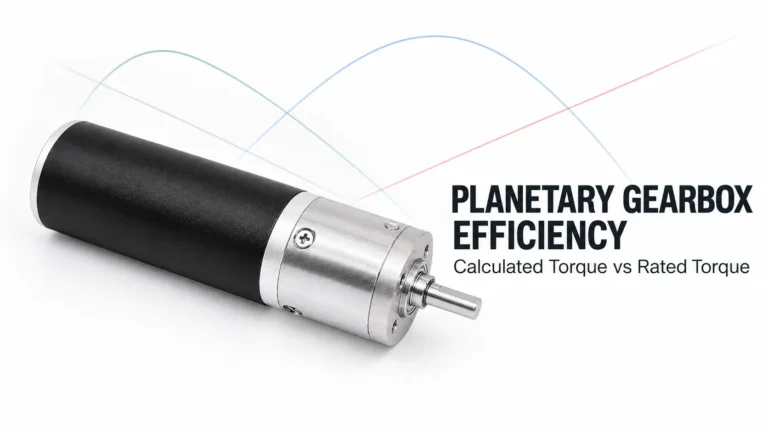
The nominal ratios of multiple stages are multiplied, but the total gearbox efficiency is the product of the individual stage efficiencies. Neugart’s multi-stage gearbox reference also explains why efficiency generally decreases as additional stages are introduced.
Why Should a Two-Stage Gearbox Not Be Assigned a Generic Efficiency?
TSL MOTOR’s GPA16 data, for example, specifies 81% maximum efficiency for a two-stage 11.76 configuration and lists reduction, absolute reduction, continuous torque, intermittent torque, and efficiency as separate values. The stage-count comparison below illustrates the design principle discussed in the source draft:
| Stages | Nominal Ratio | Max Efficiency |
| 1 Stage | 3.43:1 | 90% |
| 2 Stages | 11.76:1 | 81% |
| 3 Stages | 40.30:1 | 73% |
This does not prove that every stage loses exactly 9%, and those values must not be copied directly onto the TSL Motor Ø16 mm gearbox. They demonstrate a more important principle: efficiency must come from data or testing for the specific gearbox and operating point, not from a generic claim that every planetary gearbox is 90%, 95%, or 97% efficient.
How Should Usable Continuous Output Torque Be Determined?
An efficiency-corrected motor-side calculation is only one limit. The gearbox also has a mechanical torque rating. A more useful continuous-duty check is:
Allowable Continuous Torque = Min(Calculated Output Torque, Gearbox Rated Continuous Torque)
If the motor-side calculation gives 1.5 N·m but the gearbox is rated for 1.0 N·m continuous torque, the continuous output must not be specified as 1.5 N·m.
This is why a proper gearhead datasheet separates reduction ratio, number of stages, maximum continuous torque, intermittent torque, and maximum efficiency.
Gear ratio is not a gearbox torque rating.
A More Reliable Planetary Gearbox Sizing Sequence
ssume the application requires:
| Requirement | Value |
| Motor operating speed | 6,000 rpm |
| Required output speed | 250 rpm |
| Motor operating torque | 0.05 N·m |
| Required continuous output torque | 0.70 N·m |
- Calculate Target Reduction Ratio: i = 6000 / 250 = 24:1
- Determine Stage Combination: i = 5.4 * 4.3846 ≈ 23 .68:1
- Calculate Actual Output Speed: Speed = 6000 / 23.68 ≈ 253.4 rpm
- Estimate Output Torque: Torque = 0.05 * 23.68 * 0.80 = 0.95 N ·m
- Check the gearbox mechanical limit. Continuous gearbox torque must be at least 0.70 N·m.
- Verify the remaining operating limits. Check input speed, radial and axial loads, temperature, backlash, duty cycle, lubrication, and required service life.
Only after all six checks pass can the 23.68:1 gearbox be considered suitable for the application.
Conclusion
The basic planetary gear ratio equation is straightforward, but a reliable gearbox selection cannot end with i = 1 + (Zr / Zs). The tooth combination must satisfy the required center distances and assembly conditions; the module must suit the available diameter and load; and multi-stage ratios must be combined correctly.
The TSL Motor Ø16 mm example shows how a 44T ring, 10T sun, and 17T planet form a 5.4:1 first stage. A 44T ring with a 13T sun gives approximately 4.385:1, producing 23.68:1 across two stages.
For a customer, a useful planetary gear ratio calculation should ultimately answer four questions: What ratio is required for the target speed? Can that ratio be achieved with a feasible gear geometry? What output torque is available after losses? Can the gearbox transmit that torque continuously for the required duty and life?
Need help verifying gear ratio, output speed, torque or gearbox size? Discuss your planetary gear motor requirements with TSL Motor.
FAQ
Do three planet gears change the planetary gear ratio?
No. For a fixed ring, sun input, and carrier output, the ratio is determined primarily by the sun and ring tooth counts. The planets transmit and share load and affect assembly and capacity, but three planets do not triple the reduction ratio.
Can any sun and planet tooth counts be used if the total ratio is correct?
No. A correct ratio is only the first check. A standard planetary set must also maintain compatible sun-planet and planet-ring center distances. Planet spacing, interference, small-pinion geometry, tooth strength, and manufacturing feasibility must also be verified.
Why is actual output torque lower than motor torque × gear ratio?
A real gearbox loses power through gear meshes, bearings, lubrication, seals, and other friction. The gearbox also has its own continuous mechanical torque limit. Output torque must therefore be corrected for efficiency and checked against the gearbox rating.
Planetary Gear Motor
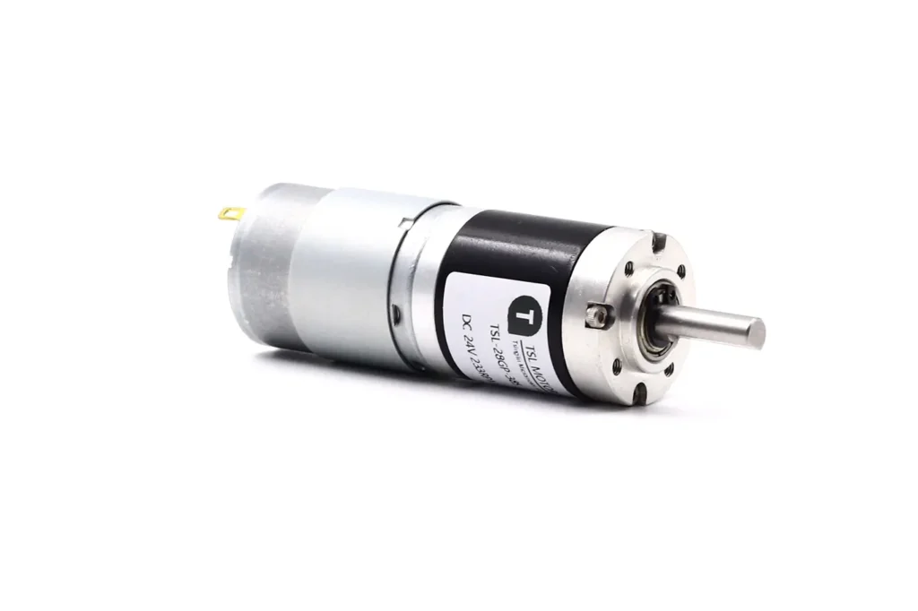
Our Planetary Gear Motors are engineered for applications requiring maximum torque density and high efficiency within a compact coaxial design. We take pride in our micro-manufacturing capabilities, offering ultra-miniature planetary gearheads starting at a world-class 4.6mm diameter, specifically designed for medical catheters, surgical tools, and precision optical instruments.