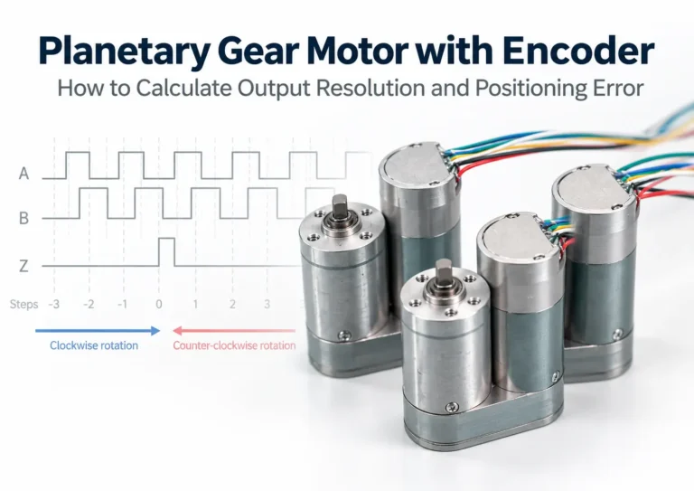
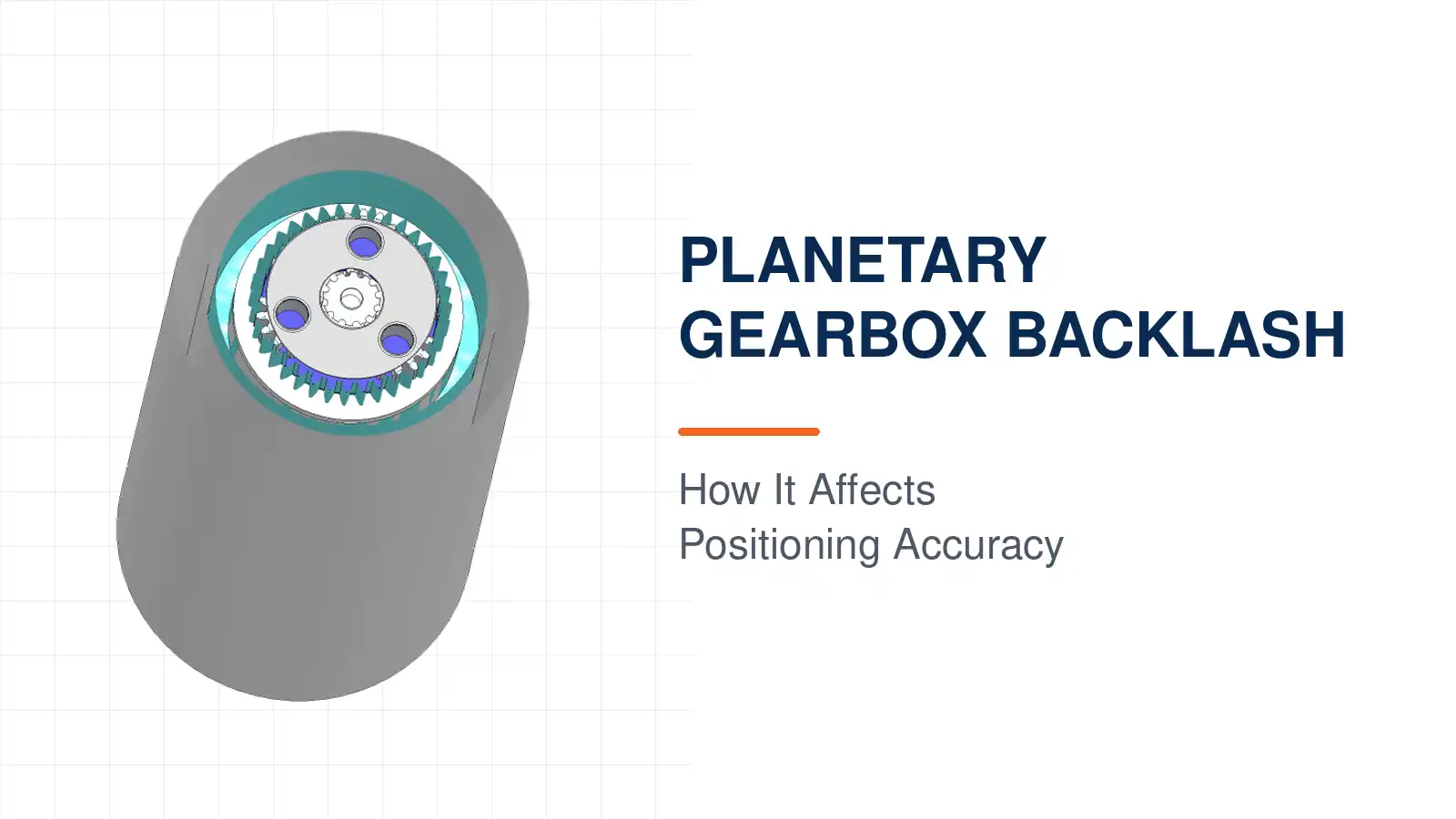

A planetary gear motor may use a high-resolution encoder and closed-loop controller, yet its output shaft may still fail to reach the commanded position immediately after the direction of motion changes.
The problem does not necessarily come from the encoder or controller. It may result from the difference between the feedback location and the actual mechanical output position.
Therefore, positioning performance cannot be evaluated only by encoder specifications such as 14-bit, 16-bit, or PPR. The complete mechanical and feedback chain must be considered:
Encoder Resolution → Encoder Location → Gearbox Backlash → Torsional Deflection → Load Radius → Actual Output Position
The real question is not simply, “How much backlash does the gearbox have?” It is:
How much output-position uncertainty does this backlash create in the actual mechanism, and can the control system observe and correct its repeatable component?
Key Takeaways
- Backlash becomes most visible when the direction of motion or load torque reverses.
- Fifteen arcminutes equals 0.25 degrees, but the resulting linear displacement also depends on the effective load radius.
- Backlash, positioning accuracy, repeatability, encoder resolution, and torsional stiffness are different specifications.
- A motor-side encoder cannot directly measure mechanical lost motion inside the gearbox.
- An output-side encoder can observe the actual output position, but it cannot eliminate physical clearance between the gears.
- Software can compensate for relatively stable reversal offsets, but it cannot eliminate mechanical errors that vary with load, temperature, and wear.
- A multi-DOF dexterous hand requires whole-hand backlash management and calibration; testing each joint individually is not sufficient.
What Is Planetary Gearbox Backlash?
Gear meshes cannot operate with absolutely no clearance under all real-world conditions. An appropriate amount of tooth-side clearance provides allowance for lubrication, thermal expansion, tooth-profile errors, and assembly tolerances.
If the clearance is too small, the gears may bind, friction may increase, lubrication may become insufficient, and noise or abnormal wear may develop. If the clearance is too large, more lost motion and positioning error will appear when the motor reverses.
KHK’s technical reference on gears explains that an appropriate amount of backlash helps accommodate tooth deflection and dimensional changes caused by operating temperature.
In a complete planetary gearbox, backlash measured at the output does not come from only one gear pair. It may include contributions from:
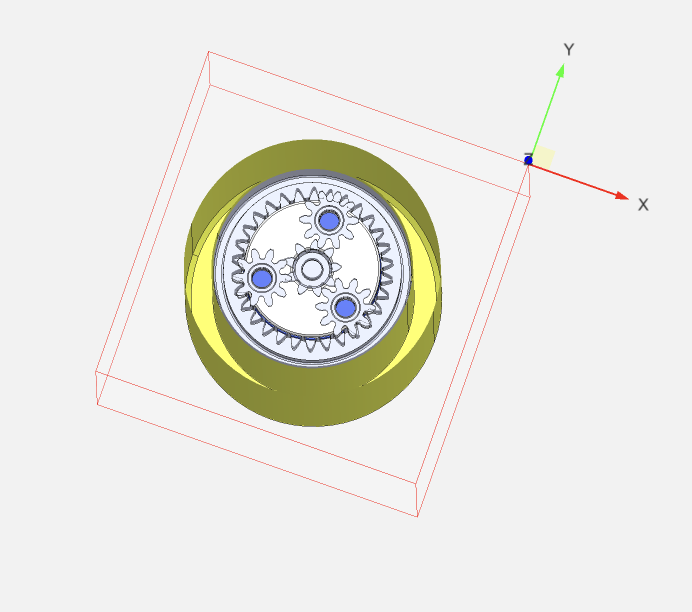
- Sun-to-planet gear mesh clearance;
- Planet-to-ring gear mesh clearance;
- Accumulated errors across multiple stages;
- Planet-pin and carrier fits;
- Bearing and output-shaft clearance;
- Gear manufacturing accuracy;
- Assembly concentricity;
- Housing and support structure;
- Lubrication condition and service wear.
For positioning systems, the most useful specification is usually angular backlash measured at the gearbox output. It is commonly expressed in degrees, arcminutes, or arcseconds.
- 1 degree = 60 arcmin
- 1 arcmin = 60 arcsec
- Therefore:
- 15 arcmin = 0.25 degrees
Why Is Backlash Most Visible During Direction Reversal?
Assume that the gearbox is rotating clockwise under load. One side of the driving and driven gear teeth remains in contact.
When the motor reverses, the previously loaded tooth flanks separate, but the opposite flanks do not engage immediately. While the gears move across this clearance, the motor and gearbox input may already be rotating, while the output shaft moves very little or not at all.
The process can be summarized as follows:
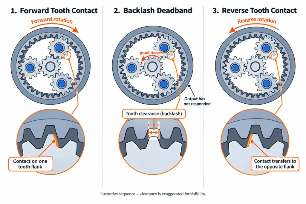
- The previously loaded tooth flanks unload;
- The input shaft begins rotating in the opposite direction;
- The gears move across the tooth-side clearance;
- The opposite tooth flanks make contact;
- The output shaft begins rotating in the opposite direction.
This region in which the input moves but the output has not yet responded is commonly described as mechanical lost motion or a reversal deadband.
A NIST study on robot-joint degradation modeling shows that backlash can temporarily disengage the driving and driven gears during direction reversal, causing output motion to lag. Changes in velocity and torque spikes may also occur when the tooth flanks re-engage.
Backlash is therefore particularly important in:
- Robot joints;
- Active joints in dexterous hands;
- Camera gimbals and positioning mechanisms;
- Inspection platforms;
- Valve actuators;
- Precision pick-and-place mechanisms;
- Medical motion systems;
- Servo axes that reverse frequently.
If a mechanism rotates continuously in one direction and the load always holds the gears against the same tooth flanks, the effect of backlash may be less visible. Once the torque direction changes, however, the previously hidden clearance can reappear.
How Do You Convert Arcminutes Into Actual Displacement?
A specification such as “15 arcmin” does not by itself indicate whether the gearbox meets the application requirement. The angular backlash must be converted into linear displacement at the load.
For a mechanism with an effective radius r and angular backlash θ:
Linear displacement is approximately equal to the effective radius multiplied by the angle in radians.
Fifteen arcminutes equals 0.25 degrees, or approximately 0.004363 radians.
The approximate geometric displacement at different load radii is therefore:
| Effective Load Radius | 5 arcmin | 10 arcmin | 15 arcmin |
|---|---|---|---|
| 50 mm | 0.073 mm | 0.145 mm | 0.218 mm |
| 100 mm | 0.145 mm | 0.291 mm | 0.436 mm |
| 200 mm | 0.291 mm | 0.582 mm | 0.873 mm |
| 300 mm | 0.436 mm | 0.873 mm | 1.309 mm |
The same 15 arcmin represents approximately 0.218 mm at a 50 mm radius, but approximately 1.309 mm at a 300 mm radius. The longer the mechanism arm, the greater the end-point displacement created by the same angular backlash.
An important distinction is that a supplier’s backlash specification usually represents the total angular movement between the two opposite tooth-contact states. The 0.436 mm value in the table can therefore be understood as the theoretical difference between approaching the same position from opposite directions at a 100 mm radius. It does not necessarily mean a fixed error of plus or minus 0.436 mm relative to a center position.
If 15 arcmin were distributed symmetrically around a nominal center, the theoretical one-sided value would be approximately 7.5 arcmin. In a real mechanism, however, the gears do not necessarily remain centered within the clearance. Gravity, friction, and external loading usually push them toward one tooth flank.
Before using a backlash value in an error budget, confirm:
- Whether the specification represents total backlash or one-sided error;
- How much reversing torque was applied during measurement;
- Whether the value was measured under no-load or loaded conditions;
- Whether the positioning tolerance is one-sided or expressed as a bidirectional peak-to-peak value.
What Is the Difference Between Backlash, Positioning Accuracy, and Repeatability?
| Parameter | Engineering Question |
|---|---|
| Backlash | How much lost motion occurs after the load direction reverses? |
| Positioning accuracy | How close is the actual position to the commanded position? |
| Repeatability | How consistently can the system return to the same position? |
| Encoder resolution | What is the smallest theoretical angular increment the sensor can distinguish? |
| Encoder accuracy | How closely does the reported encoder position match the true position? |
| Torsional stiffness | How much does the mechanism elastically twist under load torque? |
A system can have measurable backlash while still showing good repeatability when every target is approached from the same direction. Before reaching the final position, the gears are repeatedly loaded against the same tooth flanks, so the full reversal clearance does not participate in every positioning cycle.
If the same target is approached alternately from the clockwise and counterclockwise directions, the system enters two different tooth-contact states. Backlash then becomes much easier to observe.
Therefore:
- Unidirectional repeatability does not represent bidirectional positioning accuracy;
- Encoder resolution does not represent mechanical output accuracy;
- Gearbox backlash alone does not represent the complete absolute positioning error of the machine.
Why Can’t a High-Resolution Encoder Eliminate Backlash?
Consider the following system:
Motor → Motor-Side Encoder → Planetary Gearbox → Output Shaft → Load
The motor-side encoder can accurately measure the motor rotor, but it cannot directly observe mechanical lost motion inside the gearbox.
During motor reversal:
- The encoder may already detect motor rotation;
- The controller may consider the command to be in progress;
- The gears may still be crossing the reversal clearance;
- The output shaft and load may not have started moving.
This is not an encoder failure. The encoder is correctly measuring motion at its installation point.
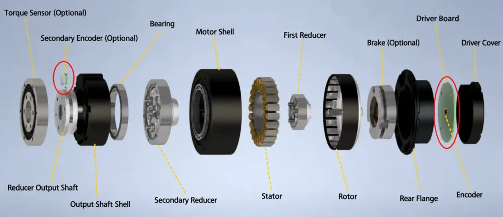
Motor-Side Encoder
A motor-side encoder is suitable for motor commutation, speed control, rotor-position measurement, and high-bandwidth inner-loop control. The reduction ratio can improve its theoretical output-equivalent resolution, but it cannot enable the encoder to measure mechanical lost motion downstream of the gearbox.
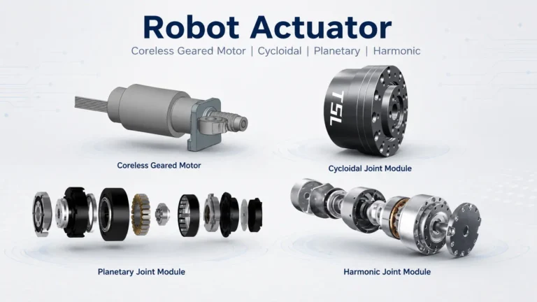
Whether the actuator uses a conventional iron-core motor or a coreless brushless planetary gear motor, motor-side Hall sensors or encoders still measure motion before the gearbox. They can support commutation and motor control, but they cannot directly observe internal gearbox backlash or the actual output-shaft position.
Output-Side Encoder
If the encoder is installed at the gearbox output, the controller can detect that the output position has not changed even when the motor has already started rotating.
Output-side feedback is therefore more appropriate for measuring robot-joint angles, bidirectional load positioning, and actual output position after an external force has been applied.
Dual-Encoder Architecture
Higher-precision actuators can use both a motor-side encoder and an output-side encoder. Motor-side feedback supports fast motor control, while output-side feedback measures the actual position after the gearbox.
A dual-encoder architecture improves the observability of mechanical errors and gives the controller more information, but it cannot physically remove clearance between the gears. The encoder technology must also be selected according to motor architecture, installation space, output signal, and control objective. Micronix provides optical, magnetic, and Hall-effect motor encoder options for different actuator configurations.
TSL-GIM4315-40 Example: 15 Arcmin Backlash and a 14-Bit Encoder
The TSL-GIM4315-40 planetary robot joint module provides a practical example for analyzing the relationship between gearbox backlash and encoder feedback.
| Parameter | TSL-GIM4315-40 |
|---|---|
| Gearbox type | Planetary gearbox |
| Gear ratio | 40:1 |
| Gear material | Steel |
| Gearbox backlash | 15 arcmin |
| Onboard encoder | 14-bit |
| Secondary output-side encoder | Supported |
| Rated torque | 15.50 N·m |
| Peak torque | 45.41 N·m |
| Rated output speed | 20 rpm |
Fifteen arcminutes equals 0.25 degrees. If the joint drives a mechanism with an effective arm length of 100 mm, the geometric lost motion is approximately:
100 × 0.004363 ≈ 0.436 mm
This value represents only the geometric conversion of 15 arcmin of backlash. It cannot be treated as the exact positioning error of the complete system. The final result is also affected by tooth-loading state, gravity direction, bearing clearance, structural deformation, controller settings, and measurement method.
What Does 14-Bit Mean?
A 14-bit encoder divides one revolution into:
2 to the power of 14 = 16,384 theoretical positions
The ideal angular increment for each position is:
360 degrees ÷ 16,384 ≈ 0.02197 degrees
This is approximately 1.318 arcmin.
If the encoder is installed on the motor side and its resolution is converted through an ideal 40:1 gearbox, the theoretical output-equivalent increment is:
1.318 arcmin ÷ 40 ≈ 0.03295 arcmin
Compared with 15 arcmin of gearbox backlash:
15 ÷ 0.03295 ≈ 455
The gearbox backlash is therefore approximately 455 times larger than the ideal output-equivalent encoder quantization increment.
This result does not mean that the system has a positioning error of “455 encoder counts.” Encoder resolution, encoder accuracy, and system positioning error are different concepts. The calculation demonstrates a more fundamental point:
Extremely fine theoretical motor-side measurement resolution does not guarantee equivalent bidirectional positioning capability at the gearbox output.
Before creating a formal positioning error budget, the actual location, accuracy, linearity, and signal-processing method of the onboard encoder must also be confirmed.
Why Does a Six-Active-DOF Dexterous Hand Require Whole-Hand Backlash Management?
For a joint-direct-drive dexterous hand, especially a design with six active degrees of freedom, testing the positioning accuracy of each actuator individually is not sufficient. Even when high-precision gears, bearings, and encoders are used, different levels of clearance and elastic deformation will remain after the complete hand is assembled.
In this context, “joint-direct-drive” means that each active joint is driven by its own independent actuator. It does not mean a completely gearless direct-drive structure.
Whole-hand error can come from:
- Tooth-side clearance in each planetary gearbox;
- Fits between output shafts and joint structures;
- Small movements in bearings and fasteners;
- Elastic deformation of finger links;
- Sensor installation errors;
- Joint-zero calibration errors;
- Motion coupling between multiple joints.
The backlash of six joints cannot be calculated by simply multiplying the backlash of one joint by six. The influence of each joint on fingertip position depends on its location, finger posture, link length, and direction of motion.
The MCP joint is located near the beginning of the finger’s kinematic chain. A small angular error at this joint changes the positions and orientations of all downstream links. Its influence on fingertip trajectory, grasp posture, and multi-finger coordination is therefore often broader than that of a distal joint.
Mechanical Backlash Management
- Control clearance in the gearbox and output connection;
- Increase bearing and joint-support stiffness;
- Prevent fastener micro-movement under repeated loading.
Sensor Design
- Define whether the sensor measures motor position or actual joint position;
- Control the concentricity, distance, and tilt between the magnet and sensor;
- Calibrate the mechanical zero and sensor zero separately.
For more information about MCP sensor position, magnetic encoder installation, and joint-angle feedback, see Optimizing MCP Joint Angle Sensors in Micro Dexterous Hands.
Control Compensation
- Identify forward and reverse offsets for each joint;
- Establish compensation for different load directions;
- Control reversal speed to reduce re-engagement impact.
Whole-Hand Calibration
- Verify fingertip position and multi-finger alignment;
- Compare forward and reverse trajectories;
- Check error changes caused by temperature rise, load, and wear.
In addition to analyzing the gearbox and encoder, engineers must evaluate bearing support, output interfaces, and mounting stiffness after actuator integration. An integrated structure such as the TSL-GIM6010-8 robot joint module provides a useful reference, but a formal positioning error budget must still be based on the final configuration’s approved mechanical drawings, electrical interface, and test data.
Whole-hand backlash management does not mean achieving absolutely zero clearance. Its purpose is to manage unavoidable clearance through mechanical design, sensing, control, and calibration so that fingertip position and grasping motion remain predictable, repeatable, and calibratable.
Why Should Backlash and Loaded Lost Motion Not Be Treated as the Same Thing?
Supplier backlash specifications are measured under defined test conditions, sometimes with no load or only a small test torque.
Under actual load, a mechanism experiences not only tooth-side clearance but also:
- Gear-tooth deflection;
- Output-shaft torsion;
- Deformation of planet pins and carriers;
- Elastic bearing displacement;
- Housing or linkage deformation.
The elastic twist can be simplified as:
Elastic twist = Load torque ÷ System torsional stiffness
The higher the load torque, or the lower the system torsional stiffness, the greater the loaded angular displacement.
The total lost motion measured during reversal may therefore include mechanical backlash, load-dependent elastic deformation, connection movement, and measurement error.
For this reason, a supplier’s low-load backlash specification cannot be treated directly as the complete output error under rated torque.
How Much Backlash Can Software Compensate?
Software can partially compensate for reversal offsets that are stable, measurable, and repeatable.
Common methods include:
- Approaching critical positions from the same direction;
- Applying different offsets for clockwise and counterclockwise motion;
- Building a direction-dependent backlash model;
- Adding pre-compensation during reversal;
- Using output-side closed-loop feedback;
- Using dual-loop control with motor-side and output-side feedback.
However, a fixed compensation value assumes that the mechanical error remains stable.
Actual backlash and loaded lost motion can vary with output torque, gravity direction, temperature, lubrication condition, gear wear, acceleration, and output-shaft loading. A compensation value obtained at room temperature and under no load may therefore be unsuitable at rated load, at temperature extremes, or after long-term wear.
Software can correct the repeatable part of a positioning offset, but it cannot turn a low-stiffness, heavily worn, or mechanically unstable transmission into a zero-backlash mechanism. It also cannot eliminate the mechanical impact created when opposite tooth flanks re-engage.
How Should Backlash Be Measured on a Prototype?
Step 1: Define the Test Conditions
Record the gearbox model, reduction ratio, temperature, lubrication condition, accumulated operating time, output load, and forward and reverse test torque.
Step 2: Measure at the Output
Use an output-side angular encoder or a dial indicator with a lever of known length. The measurement must represent the gearbox output rather than relying only on the motor-side encoder.
Step 3: Apply Forward and Reverse Torque
Apply the specified forward torque to hold the gears against one set of tooth flanks and record the output position. Then apply the same torque in the opposite direction. The difference between the two stable positions can be used to evaluate backlash or loaded lost motion.
Step 4: Repeat at Multiple Positions
Gear manufacturing errors, eccentricity, and assembly variation can cause backlash to change with output angle. A single measurement position is not sufficient.
Step 5: Add Load and Life Validation
Repeat the test under low load, rated load, after running-in, and after endurance testing. This helps separate initial mechanical backlash, loaded elastic deformation, and changes caused by wear.
How Do You Build a Positioning Error Budget?
Instead of starting with a requirement such as “we need a 5-arcmin gearbox,” derive the gearbox requirement from the allowable load-side error.
Assume that:
- The allowable tool-point positioning error is ±0.3 mm;
- The effective arm length is 150 mm.
The approximate allowable one-sided angular error is:
0.3 ÷ 150 = 0.002 radians
A value of 0.002 radians is approximately 0.1146 degrees, or 6.88 arcmin.
If the total allowable difference between two opposite approach directions is treated as 0.6 mm, the corresponding bidirectional peak-to-peak angle is approximately 13.75 arcmin.
A gearbox specified with 15 arcmin of total backlash would already be slightly above this simplified bidirectional peak-to-peak budget, before considering encoder accuracy, bearing clearance, elastic gear deformation, assembly error, linkage deflection, and temperature.
Increasing motor-side encoder resolution alone would therefore not satisfy the mechanical requirement. The project may require lower gearbox backlash, a shorter load radius, output-side feedback, or a different allocation of the complete machine error budget.
The allowable gearbox backlash should be derived from the system-level positioning requirement, rather than selected simply by choosing the smallest catalog value.
Positioning-System Selection Sequence
- Define the allowable load-side positioning error;
- Determine the effective load radius or mechanism geometry;
- Convert the linear tolerance into an allowable angular error;
- Allocate part of the error budget to gearbox backlash;
- Confirm the backlash definition, test torque, and temperature;
- Determine whether the encoder is installed on the motor side or output side;
- Evaluate encoder resolution and encoder accuracy separately;
- Evaluate torsional deformation under rated load;
- Determine whether backlash compensation or dual-encoder control is required;
- Perform bidirectional positioning tests on the actual mechanism;
- Complete whole-system calibration for a multi-DOF mechanism.
Common Mistakes
| Common Mistake | Why It Is Incorrect |
|---|---|
| Treating 14-bit or 16-bit as positioning accuracy | Bit depth primarily describes theoretical resolution |
| Assuming the reduction ratio eliminates backlash | The ratio changes the motion relationship but does not remove mechanical clearance |
| Treating motor position as output position | Mechanical errors inside the gearbox may remain unmeasured |
| Treating backlash as repeatability | Unidirectional repeatability can be much better than bidirectional positioning |
| Converting arcminutes into a fixed robot-position error | The effective load radius and mechanism geometry must also be considered |
| Directly adding the backlash of six joints | Each joint affects fingertip position according to the hand’s kinematics |
| Assuming one software offset can provide complete compensation | Backlash and elastic deformation vary with load, temperature, and wear |
| Testing in only one direction | Backlash becomes most visible when direction reverses |
| Measuring only under no-load conditions | Loaded lost motion also includes elastic deformation |
| Comparing supplier values without checking test conditions | Test torque, temperature, and definitions may differ |
FAQ
Can a High-Resolution Encoder Eliminate Planetary Gearbox Backlash?
No. An encoder can measure motion only at its installation point. If it is mounted on the motor side, mechanical backlash inside and downstream of the gearbox remains outside the feedback point. An output-side encoder can observe the actual output position, but it cannot physically eliminate gear clearance.
Is Planetary Gearbox Backlash the Same as Positioning Error?
No. Backlash is only one contributor to positioning error. Complete system accuracy is also affected by encoder accuracy, torsional stiffness, bearing clearance, assembly error, load, temperature, and controller tracking error.
Why Can Unidirectional Repeatability Be Good While Reverse Positioning Shows an Error?
When every move approaches the target from the same direction, the gears are usually loaded against the same tooth flanks. After the approach direction changes, the gears must cross the clearance before engaging the opposite flanks, which creates a positional difference.
Can Software Completely Compensate for Backlash?
Usually not. Stable and repeatable reversal offsets can be reduced through direction-dependent compensation or output-side feedback. Errors that vary with load, temperature, wear, and structural deformation cannot be eliminated with one fixed compensation value.
Is Individual Joint Calibration Sufficient for a Six-Active-DOF Dexterous Hand?
No. Individual joint calibration can identify local zero offsets, backlash, and sensor errors. After assembly, the complete hand must still be tested for multi-joint error propagation, fingertip position, multi-finger alignment, different grasp forces, and different hand postures.
Conclusion
Planetary gearbox backlash becomes most visible when the direction of motion or load torque changes. The same angular backlash can create very different end-point displacements at different load radii. Positioning performance therefore cannot be determined from the gearbox’s arcminute specification alone.
A high-resolution motor-side encoder can provide fine rotor-position feedback, but it cannot directly observe mechanical lost motion downstream of its measurement point. An output-side encoder improves the observability of actual output position, while lower mechanical backlash reduces the reversal deadband. These two approaches are complementary in precision positioning systems.
Before selecting an actuator, define the allowable output error, effective load radius, continuous and peak torque, reversing frequency, operating temperature, backlash requirement, encoder location, duty cycle, and expected life. Engineers can first compare planetary gear motor families with different sizes and feedback configurations, after which TSL Motor can evaluate standard solutions, output-side feedback, and application-specific low-backlash configurations.