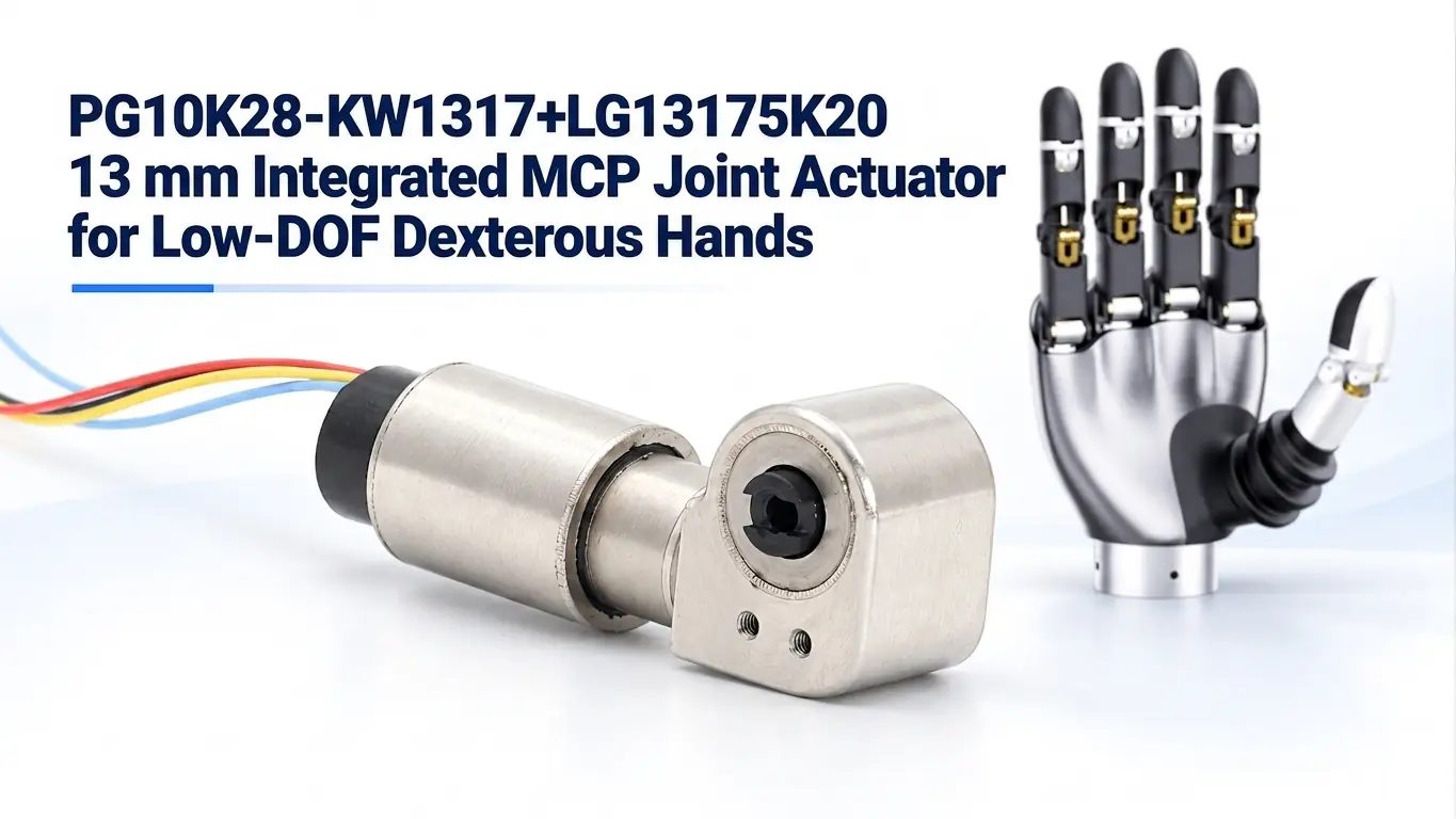

In a low-degree-of-freedom dexterous hand, the metacarpophalangeal (MCP) joint is usually one of the most important actively driven joints. Located at the base of the finger, it produces the large flexion and extension motion that brings the finger toward the palm during grasping.
Because the MCP joint sits close to the palm, its actuator must deliver useful joint torque while sharing limited space with other motors, wiring, electronics and structural components.
A human-like MCP joint can include both flexion/extension and abduction/adduction. Compact low-DOF hands, however, may actively drive only the flexion/extension axis to reduce the number of actuators and simplify the mechanism. The actuator described here is intended to drive one rotary MCP axis—typically flexion/extension—not to replace both MCP degrees of freedom with a single module.
Research published in Nature Communications also describes MCP rotation in terms of separate flexion/extension and abduction/adduction motions: Integrated Linkage-Driven Dexterous Anthropomorphic Robotic Hand.
At a Glance
MCP actuation is not simply a motor-selection problem. Developers must package the motor, reduction system, output support, position feedback, driver and communication wiring into a compact and repeatable joint assembly. If the worm and worm wheel are supplied as exposed components and aligned by the customer, errors in center distance, bearing support and assembly tolerances can cause looseness, uneven meshing or inconsistent joint behavior.
TSL MOTOR’s 13 mm robot hand actuator with integrated driver and encoder combines a 13 mm coreless BLDC motor, reduction mechanism, encoder, motor driver and housed worm-drive output in one MCP-joint module. It uses a UART + SPI interface configuration with a specified communication rate of 0.33 Mbps and is supported by TSL MOTOR’s self-developed PC software for testing, configuration and application development.
The platform has entered stable volume production.
What the MCP Joint Does in a Low-DOF Dexterous Hand
The MCP joint establishes the main posture of the proximal phalanx. When the joint flexes, the finger closes toward the palm and contributes to enveloping, power and pinch grasps. When it extends, the finger reopens and creates clearance for object release or the next grasp.
In a fully anthropomorphic mechanism, the MCP joint may provide two rotations:
- Flexion and extension;
- Abduction and adduction.
In a low-DOF dexterous hand, designers often reduce actuator count by prioritizing the axis that contributes most directly to closing the finger. This simplification can reduce cost, wiring and control complexity, but it also limits independent lateral finger motion.
Research into adaptive robotic hands confirms this trade-off: reducing the actuator-to-joint ratio simplifies the mechanism, while independent control of every joint is no longer available. See An Adaptive Actuation Mechanism for Anthropomorphic Robot Hands.
The first integration question should therefore be whether the MCP axis is:
- Independently driven;
- Mechanically coupled to another joint;
- Part of an underactuated grasping mechanism.
The 13 mm module supplies controlled rotary motion. The customer’s linkage, finger geometry and joint lever arm determine how that motion becomes joint angle and fingertip force.
Why MCP Actuation Is Difficult to Package
The MCP region generally offers more space than the PIP or DIP joints, but the available volume is still restricted by adjacent fingers, palm structures, control electronics and wiring.
A practical MCP actuator must address several requirements simultaneously:
- Sufficient reduction for useful joint torque;
- Controlled bidirectional movement for repeated opening and closing;
- Position feedback for joint control;
- Compact motor-driver electronics;
- Limited cable volume across multiple fingers;
- Stable worm-and-wheel alignment;
- Repeatable production assembly;
- Convenient commissioning and diagnostic access.
A motor alone does not solve these requirements. If the customer must separately source the encoder and driver, design the worm-drive housing, align the gear pair and develop commissioning software, a large part of the engineering burden remains with the hand manufacturer.
The purpose of an integrated module is to move these functions into a matched and repeatable actuator assembly.
The TSL MOTOR 13 mm MCP Joint Module
The TSL MOTOR 13 mm MCP joint actuator, model PG10K28-KW1317+LG13175K20, integrates a 13 mm coreless BLDC motor, a 28:1 planetary gearbox, a 20:1 worm-gear stage, an encoder and a motor driver into one compact actuator assembly.
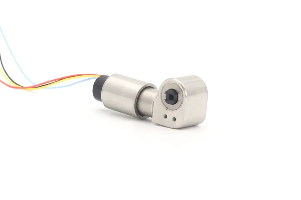
The combined reduction ratio is 1:560. At 12 V, the complete actuator provides a rated output speed of 30 ±10% rpm and a rated output torque of at least 2,500 g·cm. The worm-drive section uses a machined steel housing to establish the relative position of the worm, worm wheel and output support before the module reaches the customer’s assembly line.
The actuator supports a UART + SPI interface configuration with a specified communication rate of 0.33 Mbps. It can be controlled by the customer’s MCU after integration of the corresponding communication protocol.
The rated torque and rated speed refer to the actuator output under the specified test conditions. The actual MCP joint speed, angular range and fingertip force also depend on the finger linkage, effective lever arm, joint angle, friction and mechanical load.e limit, encoder configuration, mechanical interface and firmware parameters must be confirmed against the selected production version. These specifications should not be inferred from the 13 mm motor diameter alone.
Why the Worm Drive Has an Integrated Housing
An exposed worm and worm wheel give customers greater structural freedom, but they also make the customer’s hand structure responsible for several precision relationships.
The surrounding structure must:
- Maintain the correct center distance;
- Keep the worm and wheel shafts aligned;
- Support the output shaft;
- Prevent the gear pair from separating under load;
- Maintain consistent gear engagement during repeated reversals.
Small deviations can appear as excessive play, uneven tooth contact, wobble or inconsistent behavior among fingers.
TSL MOTOR added a dedicated housing around the worm-drive section to reduce this customer-side assembly work. The housing establishes the relative positions of the worm, worm wheel and output support before the actuator reaches the customer’s production line.
This provides three practical benefits:
- Fewer precision parts and alignment steps for the hand manufacturer;
- More consistent gear-mesh geometry across joints and production batches;
- Reduced assembly-induced wobble and more stable output support.
The housing should not be described as eliminating all backlash. Worm-drive clearance, bearing clearance, elastic deformation and the customer’s final finger structure still affect total lost motion.
Its main value is controlling the transmission geometry and removing a major source of installation variation. TSL MOTOR’s development from exposed transmissions to integrated joint modules is described in Robotic Hand Worm Gear Actuator Evolution.
How the Integrated Encoder and Driver Reduce Development Work
Position feedback is essential when the controller must move the MCP joint to a commanded angle or compare commanded and measured movement.
Integrating the encoder with the motor and transmission creates a defined sensing architecture and reduces the need for the customer to design a separate motor-side sensor bracket and installation reference.
The integrated driver performs BLDC commutation and motor control close to the actuator. This reduces the need for a separate multi-channel driver board and shortens the connections between the driver and motor.
In a dexterous hand with several active joints, these changes can reduce:
- Control-board space;
- Connector count;
- Motor wiring;
- Assembly work;
- Driver-to-motor matching effort.
Integration does not eliminate system-level validation. The hand controller still needs appropriate command scheduling, power distribution, communication management, joint limits and fault handling.
Mechanical end stops and software position limits should be defined for the completed finger because the actuator cannot determine the safe joint range from motor information alone.
Developers comparing other joint architectures can also review TSL MOTOR’s robot joint module range and motor-driver solutions.
UART + SPI Communication at 0.33 Mbps
The module uses a UART + SPI interface configuration with a specified communication rate of 0.33 Mbps. Commands and actuator information can therefore be exchanged digitally instead of controlling the motor only through analog voltage or discrete direction signals.
For a multi-finger hand, communication performance must be evaluated at the system level rather than from the nominal bit rate alone.
Developers should confirm:
- Which signals are transmitted through UART and which use SPI;
- Addressing and bus topology when multiple modules are connected;
- Command and feedback packet lengths;
- Required controller update rate;
- Timeout, checksum and fault-response behavior;
- Cable length, grounding and electromagnetic compatibility;
- Startup sequence;
- Recovery behavior after communication interruption.
The 0.33 Mbps figure describes the specified communication rate. It should not be presented as the mechanical response rate or closed-loop bandwidth of the MCP joint.
Actual joint response also depends on the firmware, control-loop settings, reduction ratio, load inertia, friction and finger mechanism.
Self-Developed PC Software for Setup and Development
TSL MOTOR provides self-developed PC software to support actuator setup, testing and application development.
During prototype development, customers can communicate with the module without first building their own complete control interface. Depending on the confirmed firmware version, the software can provide a development environment for:
- Connection testing;
- Command input;
- Motion observation;
- Parameter configuration;
- Position and direction checks;
- Basic troubleshooting.
Project-specific functions should be verified against the relevant firmware version before being included in final customer documentation.
The software is particularly useful when development moves from a single actuator on a bench to several modules installed in a complete hand. Engineers can first verify each actuator individually and then check addressing, movement direction, position feedback and joint limits before integrating the hand with the main robot controller.
How the Module Simplifies Customer Installation
The installation advantage is not limited to a shorter bill of materials. The module transfers several tolerance-sensitive tasks from the customer’s production line to the actuator manufacturer:
- Worm-and-wheel positioning is established inside the module;
- Output support is incorporated into the housing;
- Encoder installation is standardized;
- The driver and motor are matched as one system;
- A defined digital interface replaces multiple discrete control connections;
- Commissioning can begin using the supplied PC software.
The customer remains responsible for:
- Finger-side mounting;
- Output coupling;
- Mechanical joint stops;
- Cable routing;
- Complete-hand control;
- System-level safety and fault handling.
The housing should be installed without distortion, and the finger linkage should not force the output into an eccentric or misaligned condition.
If an external lever or linkage applies radial or axial loads to the output, those loads must be checked against the confirmed output-support design.
Stable Volume Production and NDA-Safe Market Evidence
This 13 mm actuator is not only a concept sample. It has entered stable volume production for dexterous-hand projects.
Production status is important because volume manufacturing introduces requirements that a one-off prototype may not reveal, including:
- Consistent worm-gear meshing;
- Repeatable encoder installation;
- Wiring reliability;
- Firmware configuration control;
- Joint-to-joint consistency;
- Batch-to-batch mechanical performance.
TSL MOTOR is bound by confidentiality agreements and therefore does not identify customer brands or disclose protected project details.
The appropriate public statement is:
The module is in stable volume production and is used in low-DOF dexterous-hand products visible in the Chinese market.
This statement communicates commercial production experience without implying public authorization or endorsement from any named dexterous-hand manufacturer.
Recommended Prototype Validation
Before releasing the module into a production hand, it should be validated in the complete finger and palm structure.
The validation plan should include:
- MCP angular range and mechanical end-stop position;
- No-load and loaded opening and closing behavior;
- Output play measured at the finger rather than only at the actuator;
- Joint temperature under the actual duty cycle;
- Repeated reversing and grasping cycles;
- Communication stability with all intended modules connected;
- Power-supply behavior during simultaneous joint acceleration;
- Encoder direction, zero position and homing strategy;
- Response to blocked motion, overload and communication timeout;
- Cable movement and strain relief throughout the joint range;
- Consistency among fingers and production batches.
Fingertip force must be measured on the completed finger. It cannot be declared from actuator torque alone because linkage ratio, lever arm, joint angle, friction and structural deformation all affect the force delivered at the contact point.
Information Required for MCP Joint Integration
To evaluate the module for a new dexterous-hand project, customers should provide:
- Required MCP angular range;
- Target opening and closing time;
- Continuous and peak joint torque;
- Finger-linkage geometry and effective lever arm;
- Available actuator envelope;
- Supply voltage and current limits;
- Number of actuators on the communication network;
- Required control and feedback update rate;
- Expected duty cycle and ambient temperature;
- CAD files for the mounting and output interfaces;
- Prototype quantity and projected production volume.
These inputs allow the motor winding, reduction system, feedback configuration, firmware limits and mechanical interface to be evaluated as one system instead of as isolated components.
Conclusion
An MCP actuator for a low-DOF dexterous hand must do more than generate torque. It must fit near the palm, reverse repeatedly, report its position, communicate with the hand controller and remain mechanically consistent across multiple fingers and production batches.
TSL MOTOR’s 13 mm MCP joint module integrates a coreless BLDC motor, encoder, motor driver and housed worm-drive output. The housing reduces customer-side precision assembly and helps control the alignment that affects wobble and transmission consistency.
UART + SPI communication at a specified rate of 0.33 Mbps and TSL MOTOR’s self-developed PC software simplify commissioning and application development.
The module is already in stable volume production for low-DOF dexterous-hand applications. Because customer identities are protected by NDAs, TSL MOTOR discusses the production platform and its engineering results without naming the brands using it.
To evaluate the actuator for a new MCP mechanism, provide the joint envelope, torque, angle, duty cycle, linkage and control requirements through the TSL MOTOR project contact page.
FAQ
What does MCP mean in a robotic hand?
MCP means metacarpophalangeal joint, the joint at the base of a finger. In a low-DOF hand, its flexion/extension axis is commonly prioritized to close and reopen the finger.
Does one 13 mm module provide both MCP degrees of freedom?
No. The module drives one rotary axis. If independent flexion/extension and abduction/adduction are required, the hand needs an additional actuator or separate multi-axis mechanism.
Why is the worm-drive housing important?
It locates and supports the worm, worm wheel and output as an assembly. This reduces customer-side precision alignment and helps limit wobble and production variation, although it does not eliminate every source of backlash.
Can I control the actuator with my own MCU and request the communication protocol?
Yes. The actuator can be controlled through the customer’s MCU using the supported communication interface. Customers can contact TSL MOTOR to request the corresponding communication protocol and integration information. TSL MOTOR’s self-developed PC software is also available to support initial communication testing, parameter configuration and actuator development.