
Distraction osteogenesis is a surgical method used to lengthen or realign bone by gradually separating two bone segments after an osteotomy. As the distance increases in controlled increments, new bone tissue forms within the distraction gap. The procedure is used in limb lengthening, bone transport and deformity correction.
Traditional external fixators are often adjusted manually by turning nuts or threaded struts several times per day. A motorized external fixation system can divide the prescribed displacement into smaller automatic movements, helping reduce manual adjustment errors and improving the repeatability of the correction trajectory.
At a Glance
A motorized distraction system needs to produce controlled axial movement against resistance from muscles, soft tissue and the external fixation structure. It must combine sufficient push-pull force with low-speed incremental motion, repeatable positioning and reliable communication with the medical device controller.
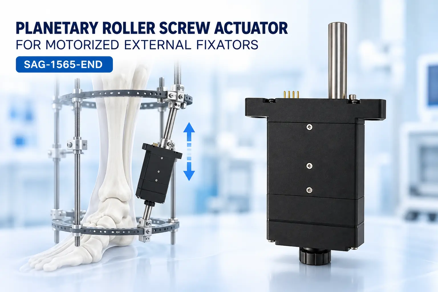
The SAG-1565-END planetary roller screw actuator combines a 12 V coreless brushed motor, planetary reduction gearbox and planetary roller screw in a compact linear drive. It provides a rated push-pull force of 300 N, a maximum force of 500 N, a 12 mm stroke, repeat positioning accuracy of ±3 μm and RS485 communication.
What Is Distraction Osteogenesis?
The U.S. National Library of Medicine defines distraction osteogenesis as bone lengthening through gradual mechanical distraction. In an external fixation system, bone pins or wires connect the bone segments to a rigid frame, while adjustable struts control the relative position of the segments.
The bone is not separated to its final distance in one movement. Instead, the frame is adjusted in small increments over an extended period. Oxford University Hospitals notes that a typical correction rate may be approximately 1 mm per day, although the actual rate must be determined and adjusted by the clinical team according to the patient’s condition and bone formation.
How the Actuator Works in an External Fixator
The SAG-1565-END can be installed as a powered strut or as the drive element of an adjustable external fixation rod. Its mechanical transmission path is:
Coreless DC motor → planetary gearbox → planetary roller screw → linear output rod → external fixation strut → fixation ring and bone pins → controlled bone-segment displacement
The coreless motor generates high-speed rotary motion. The planetary gearbox reduces the speed and increases the available output torque. The planetary roller screw then converts this rotation into slow axial movement. As the actuator extends or retracts, it changes the distance or angle between selected points on the external fixation frame.
In a multi-strut external fixator, several actuators can be coordinated to perform axial lengthening, angular correction, lateral translation or rotational correction. Research into electromotor-driven parallel external fixators shows that motorized struts can follow a planned correction trajectory while reducing dependence on repeated manual adjustment.
Why Use a Planetary Roller Screw?
A conventional lead screw relies mainly on sliding contact between the screw and nut. A planetary roller screw uses multiple threaded rollers to distribute axial load through rolling contact. This structure is suitable for compact actuators that require relatively high axial force, controlled low-speed movement and repeated bidirectional operation.
In the SAG-1565-END, the roller screw is combined with a machined solid-steel gearbox and a compact coreless motor. This arrangement allows the actuator to generate substantially more linear force than the motor could provide through direct drive while keeping the assembly small enough for integration into a portable external fixation system.
TSL Motor also provides other coreless gear motor solutions for medical and precision motion systems where installation space and power density are important.
Why Speed Must Be Controlled by the System
which bone is continuously distracted. Clinical distraction normally occurs over days or weeks. The device controller must convert the prescribed daily displacement into short, accurately controlled actuator movements.
For example, the control system may divide a prescribed daily adjustment into several increments or a larger number of micro-increments. The actual displacement, frequency and timing must be defined by the medical device manufacturer and clinical team. They are not preset medical treatment parameters of the actuator itself.
Control and Safety Integration
The RS485 interface allows the system controller to send motion commands and coordinate multiple actuator axes. A complete external fixation system should also incorporate position verification, mechanical travel limits, current monitoring and emergency-stop logic.
Current monitoring can help identify overload or an unexpected obstruction, but motor current should not be treated as a direct measurement of bone or tissue force without system calibration. Applications requiring direct force control should add an appropriately rated load cell or force sensor.
The selected DC motor driver must support the 12 V actuator, rated current, 2 A peak current and the required direction, braking and protection functions.
Mechanical Integration Requirements
The actuator should be mounted so that the load acts along the roller-screw axis. Angular misalignment and lateral loading can increase friction, reduce positioning repeatability and shorten the service life of the screw and bearings. Spherical joints, clevis mounts or similar articulated connections can help maintain axial loading while the frame geometry changes.
The 12 mm stroke must also be checked against the required correction distance of each strut. Applications requiring a larger total displacement may need a longer-stroke customized actuator, mechanical repositioning or a different external-frame geometry.
Customization and System Validation
Different external fixators may require different stroke lengths, mounting ends, cable directions, connectors, feedback methods and communication protocols. TSL Motor can evaluate these requirements through its custom motor and actuator solutions.
Before the actuator is used in a medical product, the complete system must be tested under representative axial loads. Validation should include positioning accuracy, accumulated multi-cycle error, holding capability, temperature rise, unexpected power loss, communication interruption, mechanical overload, ingress protection and cable durability.
The SAG-1565-END is a motion component for equipment development. Compliance, risk management and clinical suitability must be assessed at the final medical-device level. More information about TSL Motor’s capabilities is available on the medical equipment motor solutions page.
Conclusion
Motorized external fixators can replace repeated manual strut adjustment with controlled, programmable linear motion. In this system, the actuator does not directly “grow bone.” Its role is to move the external fixation structure in small, repeatable increments so that the prescribed distraction trajectory can be implemented.
With 300 N rated force, 500 N maximum force, a 12 mm stroke, ±3 μm repeat positioning accuracy and RS485 communication, the SAG-1565-END provides a compact drive platform for motorized distraction and deformity-correction systems. Engineers developing an external fixator can contact TSL Motor to evaluate stroke, force, mounting, feedback and communication requirements.
FAQ
Is the SAG-1565-END implanted inside the patient?
No. This application positions the actuator as part of an external fixation system. Implantable use would require a separate design, implantable materials, sealing, biocompatibility, sterilization validation and relevant regulatory approval.
Is 500 N the continuous working force?
No. The rated push-pull force is 300 N. The 500 N value is the maximum push-pull force and should not be used as the continuous operating point.
Does the 0.4 mm/s speed determine the clinical distraction rate?
No. It is the actuator’s no-load movement capability. The medical device controller determines when and how far the actuator moves according to the prescribed treatment plan.
Can several actuators be used in one external fixator?
Yes. Multiple RS485-controlled actuators can potentially be coordinated in a parallel external fixation structure. The frame geometry, calibration method, synchronization accuracy and failure protection must be validated by the equipment manufacturer.
Can the stroke and mounting interfaces be customized?
Yes. Stroke, mounting ends, cables, connectors and control requirements can be evaluated according to the customer’s external fixation system and expected production volume.