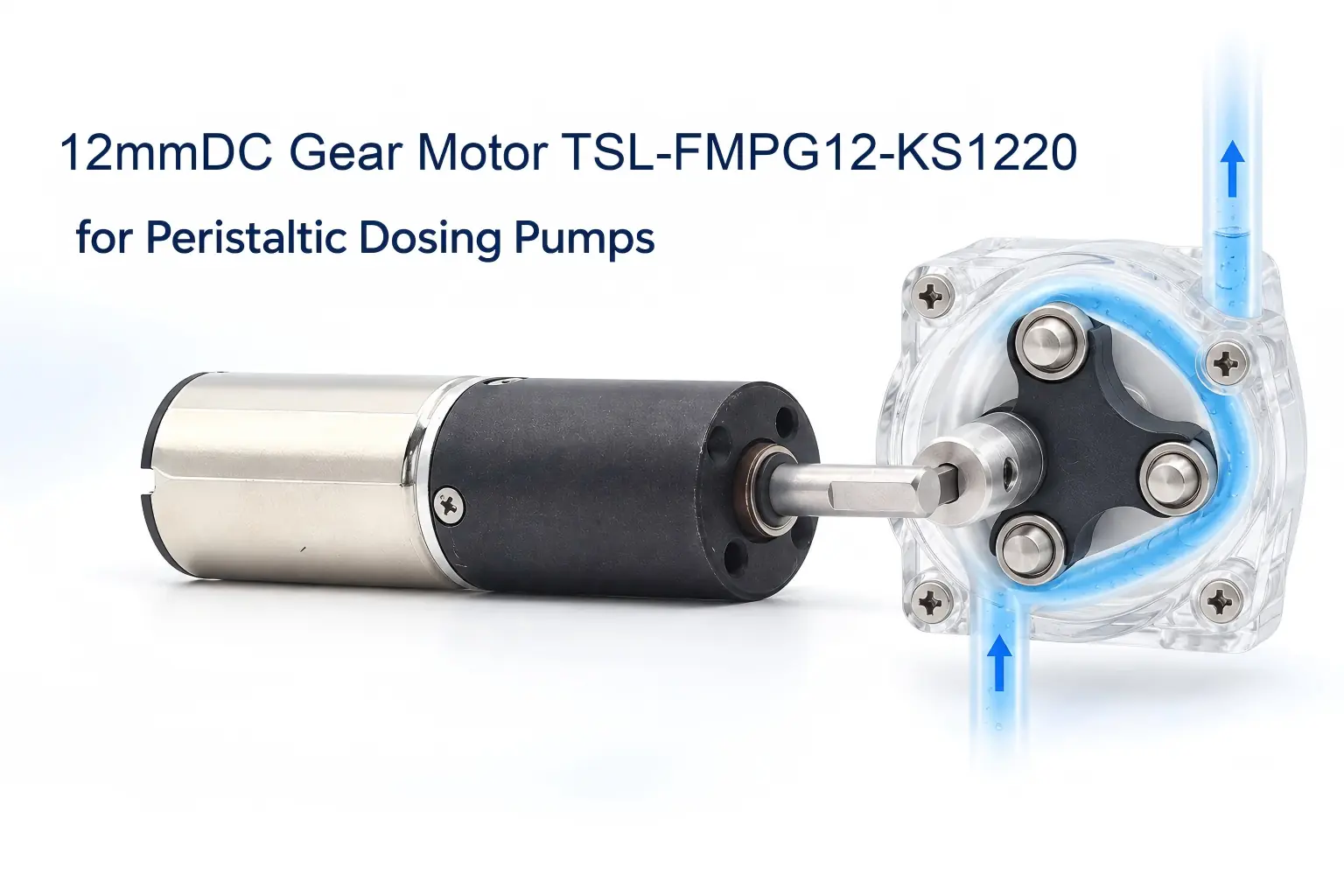

A miniature peristaltic dosing pump uses rotating rollers to compress flexible tubing. As the rollers move along the tube, they create sealed pockets that carry reagents, cleaning fluids or additives from the inlet to the outlet. The motor does not contact the liquid directly. It is installed behind the pump head and drives the roller rotor through its output shaft.
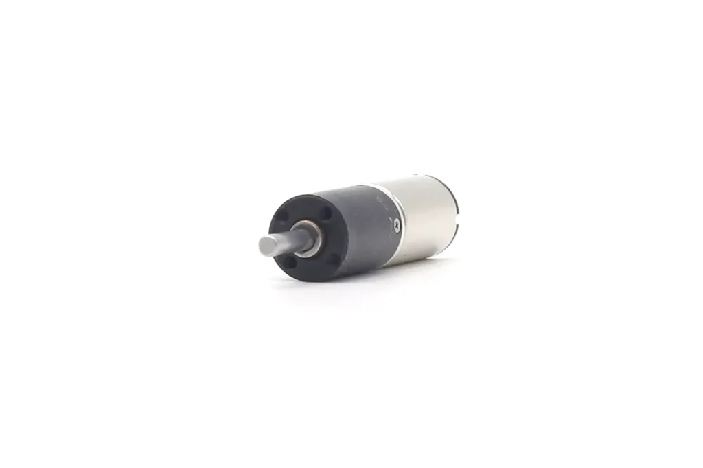
In this system, the motor must perform three specific functions: reduce the motor speed to the required pump-head speed, provide enough torque to compress the tubing, and connect reliably to the pump head within a restricted installation space. The TSL-FMPG12-KS1220 12mm DC gear motor combines a coreless brushed DC motor with a powder-metal planetary gearbox for this type of coaxial pump drive.
At a Glance
The TSL-FMPG12-KS1220 is normally mounted behind the peristaltic pump head. Its gearbox output shaft connects to the central rotor hub, which carries two or three rollers. As the rotor turns, the rollers press the tubing against a curved pump track and move the liquid from the inlet toward the outlet.
The motor has a diameter of 12 mm and is available in 3 V, 6 V and 12 V versions. Gear ratios range from 64:1 to 5184:1, providing no-load output speeds from 1.2 to 468.8 rpm across the available configurations. The appropriate version is selected according to the pump-head diameter, roller quantity, required flow rate and tubing-compression torque.
How the Motor Drives the Peristaltic Pump
The mechanical power path inside the pump is:
Coreless motor rotor → planetary gearbox → gearbox output shaft → pump rotor hub → roller carrier → compression rollers → flexible tubing
The coreless motor first generates high-speed rotation. The planetary gearbox reduces this speed and transfers the increased output torque to the 3 mm D-shaped output shaft.
The output shaft fits into a matching D-shaped bore or clamping hub in the center of the pump rotor. This connection allows the motor and pump rotor to turn together without the hub slipping on the shaft.
Two or three rollers are normally installed around the rotor. As the rotor turns, each roller moves around the center of the pump head and presses the tubing against the curved track. Liquid ahead of the compression point is pushed toward the outlet, while the tube behind the roller returns to its original shape and draws in more liquid.
The motor does not pump the liquid by itself. It rotates the roller carrier, while the pump rotor, rollers, tubing and curved housing create the peristaltic pumping action.
Connecting the Output Shaft to the Pump Rotor
According to the TSL-FMPG12-KS1220 mechanical drawing, the gearbox output interface includes:
| Output interface | Drawing dimension |
|---|---|
| Output shaft | Ø3 mm D-shaped shaft |
| D-flat dimension | 2.8 mm |
| D-shaped engagement length | 7 ± 0.1 mm |
| Total shaft extension | 13.5 mm |
| Front locating boss | Ø5 ± 0.05 mm |
| Locating-boss length | 1.6 mm |
| Mounting holes | Four M2 threaded holes, 2.5 mm deep |
The pump rotor can be connected in three main ways.
Direct D-Bore Connection
A matching D-shaped bore is machined or molded into the center of the pump rotor hub. The rotor is then installed directly onto the motor shaft.
The D-flat transfers torque and prevents the rotor from slipping. This arrangement uses few components and keeps the total axial length short, making it suitable for small pump heads with moderate tubing-compression loads.
The rotor hub can be manufactured from engineering plastic, aluminum or stainless steel. The D-bore tolerance must be controlled so the connection does not become loose after repeated starts, stops and reversals.
Clamping-Hub Connection
A clamping hub can secure the rotor to the D-shaped shaft. Compared with a single set screw, a clamping hub distributes the holding force more evenly and makes it easier to adjust the axial position of the pump rotor.
If a set screw is used, it should press against the flat surface of the D-shaped shaft rather than the round surface. Excessive set-screw force should be avoided because it can pull the rotor away from the shaft centerline.
Coupling to an Independently Supported Pump Shaft
For pump heads with higher compression forces or replaceable pump-head cartridges, the motor shaft can drive a separate pump shaft through a miniature coupling.
The pump shaft is supported by its own bearing or bearing pair, and the roller rotor is mounted on that shaft. This arrangement is longer than a direct connection, but it prevents most of the tubing-compression load from acting directly on the gearbox output bearing.
It is the preferred structure for continuous operation, higher tube compression or pump heads with a longer rotor overhang.
Supporting the Tubing-Compression Load
When a roller compresses the tubing, the tube generates a reaction force against the roller. This force travels through the roller pin, carrier and rotor hub to the central shaft, creating both output torque and a changing radial load.
If the roller rotor is mounted directly on the motor output shaft, the gearbox output bearing must transmit torque while also supporting the radial load. This arrangement may be acceptable for a very small pump head, but only after confirming the gearbox’s permitted radial load and the distance between the rotor and the gearbox face.
A more robust pump structure uses the following arrangement:
- The motor is fastened to the rear pump plate with four M2 screws.
- The Ø5 mm front boss locates the motor concentrically with the pump head.
- The pump rotor is supported by a bearing in the pump housing.
- The D-shaped shaft or coupling transfers torque to the supported pump shaft.
- The pump-head bearing and housing carry most of the tubing-compression reaction force.
This arrangement reduces shaft deflection, gearbox noise and output-bearing wear. It also helps maintain consistent roller-to-tube compression around the pump track.
What the Planetary Gearbox Does in the Pump
The speed of the coreless motor is much higher than the speed normally required by a miniature peristaltic pump head. The planetary gearbox converts the motor’s high-speed rotation into lower output speed and higher usable torque.
The approximate pump torque can be expressed as:
Pump torque ≈ tubing compression force × effective rotor radius + friction torque + pressure-related torque
Where:
- Tubing compression force is the equivalent tangential force required to squeeze the tube.
- Effective rotor radius is the distance from the pump center to the roller contact point.
- Friction torque includes losses in the rollers, tubing and pump track.
- Pressure-related torque is the additional load created by outlet backpressure.
A larger pump-head diameter increases the torque arm. Harder tubing, thicker tube walls and greater occlusion also increase the required motor torque. For this reason, motor selection must include a starting-torque test using the actual pump head and tubing.
Matching Output Speed to Pump Flow
When the gearbox output shaft is connected directly to the pump rotor at a 1:1 ratio, the gearbox output speed is also the pump-head speed.
The initial flow-rate relationship is:
Flow rate = calibrated volume per pump-head revolution × pump-head speed
The required pump-head speed can therefore be calculated as:
Pump-head speed = target flow rate ÷ calibrated volume per revolution
The gear ratio can be screened according to the following operating ranges:
| Pump-head operation | Initial ratio range | Function in the pump |
|---|---|---|
| Fast priming or tube flushing | 64:1–144:1 | Provides higher roller-rotor speed |
| General reagent dosing | 256:1–864:1 | Balances pump speed and tubing-compression torque |
| Slow, low-volume delivery | 1024:1–5184:1 | Reduces rotor speed without relying on an extremely low PWM duty cycle |
These ranges are only starting points. The selected winding, tubing-compression torque and outlet pressure must also be considered.
If an additional gear pair is installed between the gearmotor and the pump rotor, the external transmission ratio must be included when calculating the final pump-head speed. However, a coaxial direct connection is normally preferable for a 12 mm pump because it reduces components, side space and additional backlash.
A high reduction ratio does not mean that the gearbox can produce unlimited torque. The operating torque must remain below the gearbox’s allowable continuous mechanical torque, and stall torque must not be used as a normal operating point.
Dosing, Reversing and Stall Detection
Time-Based Dosing
For basic dispensing applications, PWM can regulate motor speed while the controller determines the dose from the calibrated running time.
This approach is simple, but the complete pump must be calibrated because tubing condition, backpressure and liquid properties can change the delivered volume.
Encoder-Based Dosing
An encoder can be integrated at the rear of the motor when the system needs to control the number of pump-head revolutions.
For an encoder mounted on the motor shaft:
Counts per pump-head revolution = encoder counts per motor revolution × gearbox ratio
The controller can use these counts to regulate rotor speed, command a defined number of pump revolutions and detect whether the motor is rotating.
Encoder feedback improves rotational control, but it does not measure the liquid directly. Tube elasticity, wear and pressure variation can still change the actual dose. Additional calculations are explained in the planetary gear motor encoder resolution guide.
Short Reverse Movement
A brushed DC motor can reverse through an H-bridge driver. After completing a dose, the motor can briefly reverse the roller rotor to release outlet pressure and reduce dripping.
The reverse distance must account for planetary gearbox backlash and the amount of tubing recovery. Reversing only a few motor counts may not move the pump rotor if the command remains within the gearbox backlash zone.
Stall and Occlusion Detection
Motor current rises when the pump rotor jams, the tubing is installed incorrectly or the outlet becomes blocked. The controller can monitor current and stop the motor when it exceeds the validated limit.
Texas Instruments’ brushed DC motor driver resources describe H-bridge control, PWM, current sensing and protection functions that can be used in the pump-control circuit.
Current monitoring can identify abnormal mechanical load, but it should not be treated as a direct flow measurement.
Suitable Pump-Head Configurations
The TSL-FMPG12-KS1220 is particularly suitable for:
- Miniature peristaltic pumps with the motor and roller rotor arranged on the same axis;
- Two-roller or three-roller pump heads;
- Direct-drive rotors with a matching D-shaped hub;
- Dosing pump heads with an independently supported input shaft;
- Reagent pumps in biochemical analyzers;
- Sampling and reagent pumps in water-quality instruments;
- Cleaning-fluid and waste-liquid pumps in laboratory automation;
- Small additive and concentrate dispensing modules.
It should not be connected to a large pump head, hard thick-wall tubing or a high-pressure pump head without verifying the mechanical load. These structures may produce tubing-compression torque and radial forces beyond the capacity of a 12 mm gearbox.
Prototype Validation
The complete pump prototype should be tested with the final rotor, rollers and tubing. Validation should include:
- Whether the output shaft reliably drives the rotor hub;
- Whether the D-bore or coupling slips;
- Startup at the maximum tubing-compression position;
- Output-shaft deflection under radial load;
- Motor current and flow rate at different backpressures;
- Motor and gearbox temperature rise;
- Forward, stop and reverse anti-drip behavior;
- Flow change as the tubing ages;
- Pump-head bearing and gearbox life;
- Performance consistency across multiple samples.
Testing should be completed inside the final equipment enclosure because mounting stiffness, heat dissipation and housing resonance can change the performance of the pump drive.
Conclusion
In a miniature peristaltic dosing pump, the TSL-FMPG12-KS1220 is installed behind the pump head. Its Ø3 mm D-shaped output shaft connects to the roller rotor hub or to an independently supported pump shaft. The gearbox output turns the roller carrier, and the rollers sequentially compress the tubing to move liquid through the pump.
The motor’s main function is to convert the high-speed rotation of the coreless motor into the low speed and usable output torque required by the pump head while maintaining a compact 12 mm diameter. For a reliable design, the pump-head bearing should support the tubing-compression reaction force, while the motor output shaft should primarily transmit torque.
For motor selection, customers should provide the pump-head structure, roller quantity, tubing dimensions, target speed, starting torque, outlet backpressure, duty cycle and available installation space. TSL MOTOR can evaluate the winding, gear ratio, output shaft, connector and encoder configuration. Contact TSL MOTOR for a specific pump-drive evaluation.
FAQ
Which pump component does the motor output shaft drive?
The output shaft normally connects to the central roller rotor hub. As the hub rotates, the rollers mounted on it sequentially compress the tubing.
Why does the motor use a D-shaped output shaft?
The flat surface transfers torque and prevents the rotor hub from slipping. The pump rotor should use a matching D-shaped bore or a clamping hub.
Can the roller rotor be mounted directly on the motor shaft?
It can be evaluated for a small, low-load pump head, but the gearbox’s radial-load limit must be confirmed. A pump head with higher compression force should use an independently supported shaft so the motor output shaft mainly transmits torque.
Is an additional gear transmission required between the motor and pump head?
Normally, no. The TSL-FMPG12-KS1220 already includes a planetary gearbox. A coaxial direct connection reduces size, component count and additional backlash. External gears or a timing belt are only required when the pump layout does not allow coaxial installation.